SIPLACE D系列Servicemanual.pdf - 第61页
Service Work D3 Gantry Servicemanual (internal version) SIPLACE D Series 61 4.1.3.5 Replacing Gantries Overview of gantry versions SIPLACE HF to Ma. No. A219: [03020302S] SIPLACE HF from Ma. No. A220: [030 25822S] SIPLAC…
Service Work
Gantry D3
60 Servicemanual (internal version) SIPLACE D Series
See also:
J
Handling the Hose Unlocking Tool [03047090-xx] [
J
48]
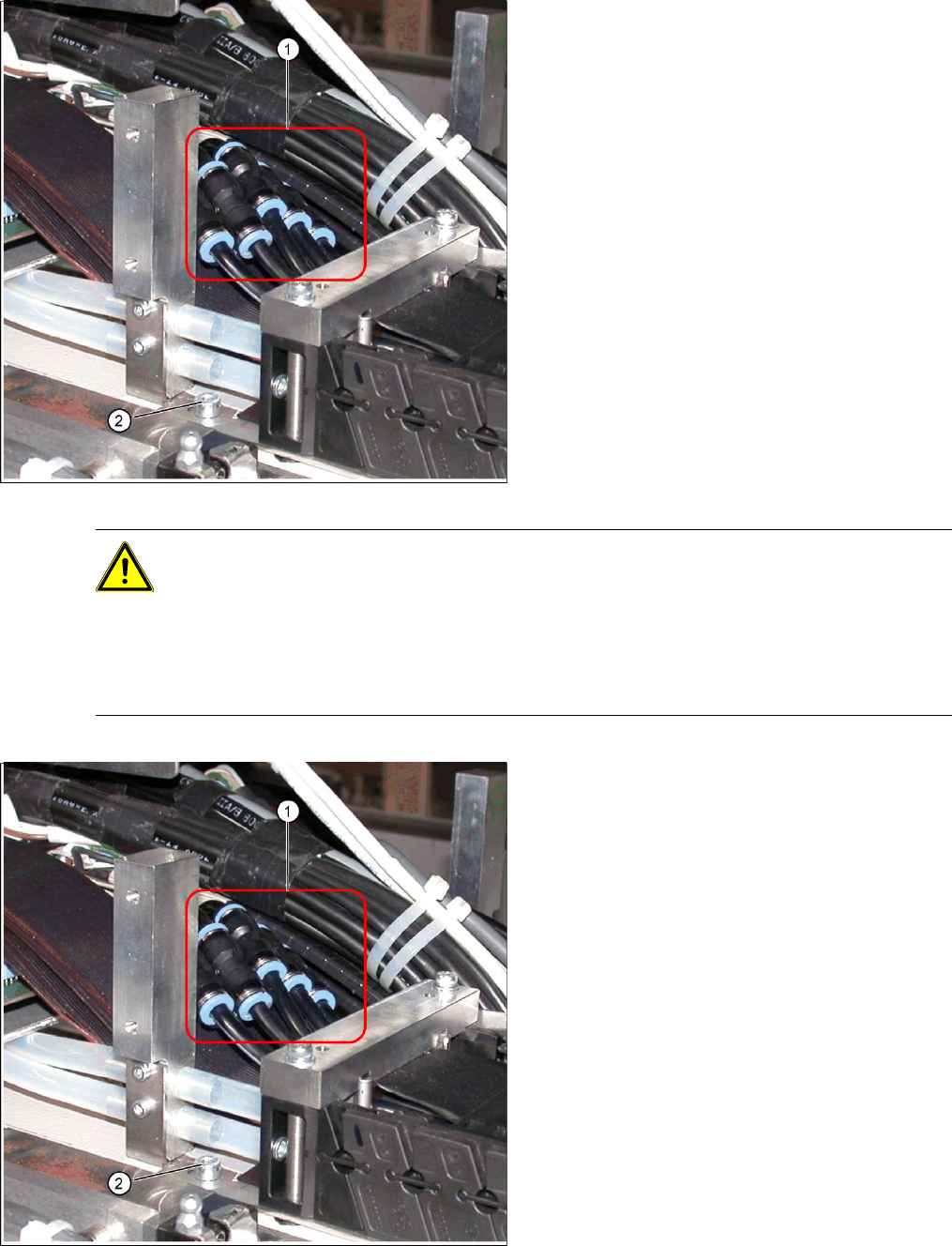
X Fit the trailing cable mount (2) onto the
machine base.
Connect the pneumatic hoses to the
pneumatic distributor in the machine
base.
The pneumatic hoses are run to the pneumatic
distributor in the machine base. The existing
pneumatic hoses, which are run in the machine,
need to be severed and connected to the trailing
cable at the exact position, with the help of hose
couplings (03049770-01) (1).
X Place the gauge at the stopper edge of the
mount and label the pneumatic hoses for the
trailing cable. See also section ( Preparing the
Trailing Cable
J
50 ) .
CAUTION: Shortening and connecting the pneumatic hoses
X Label the order of pneumatic hoses (from 1 to 7 – inside to outside). This is important to
ensure that the hoses are then correctly connected again after cutting.
X Make sure that you use the correct gauge for your gantries and that you do not cut the
pneumatic hoses too short.
X Make sure that the hose couplings are not run over one another. Use the gauge to shorten
the individual hoses to the various optimum lengths.
X Cut the pneumatic hoses of the new trailing
cable at the marked points.
X The 7 hoses of the new trailing cable are
connected to one another. Carefully separate
these from one another, up to the mount.
X Connect the pneumatic hoses for the trailing
cable with the hose couplings (1). Observe the
labeling (1-7 from inside to outside).
X Reconnect the Y motor cooling tubes to the
connection pieces.
X If you have the option "Vacuum pump",
reconnect the pneumatic hoses.
X Fasten new cable ties at the original points.
X Replace all dismantled cover plates in their
original positions.
Service Work
D3 Gantry
Servicemanual (internal version) SIPLACE D Series
61
4.1.3.5 Replacing Gantries
Overview of gantry versions
SIPLACE HF to Ma. No. A219: [03020302S]
SIPLACE HF from Ma. No. A220: [03025822S]
SIPLACE X series to Ma. No. B078: [03025822S]
SIPLACE X series from Ma. No. B079: [03039725]
SIPLACE D3, SIPLACE X4i gantry 2+4: [03039725]
SIPLACE X4I gantry 1+3: [03027255]
Preparation
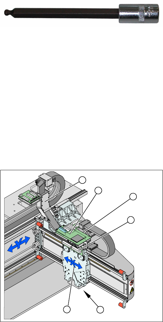
Tools and Equipment
Blue covers [00355787-xx]
Torque wrench [00376625-xx]
Set of socket wrenches [00376516-xx]
Hexagonal ball-type insertion ¼“ size 5
100 mm [00386341-xx]
see adjacent photo.
Depending upon the configuration of the machine,
you will need to remove the relevant modules,
covers and cover plates before you can dismantle
the gantry.
Legend
1. X drive (primary) with head mount
2. X mount with trailing cable
3. Head adapter board
4. Mount with PCB camera
5. Head Board
6. Trailing cable console
X Dismantle the placement head.
X Remove the head adapter board (3). The X
mount fixtures (2) are now accessible.
X Unplug the following cables from the head
board (5) and remove them from the X mount
(2):
X motor cable
X axis scanner head
Temperature sensor (if supplied).
5
5
6
1 4
3
2
Service Work
Gantry D3
62 Servicemanual (internal version) SIPLACE D Series
X Unplug the proximity switch cable (2) and pull
it forwards, out of the head mount.
X Undo the 8 screws (4 x at front/ 4x at back)
fastening the X mount (1) and pull these up
and out, together with the trailing cable.
X Loosen the two trailing cable pressure plates
on the X gantry.
X Remove the trailing cable as far as the trailing
cable console (see section (4.1.3.4 Replacing
the Trailing Cable (IGUS) for D3/X4I/X Series
from B-079 [03021065-xx]
J
48 ) ).
X Fasten the X mount at a suitable point.
CAUTION:
Make sure that the flat ribbon cable and
the pneumatic hoses are not rubbed
against any parts or folded.Look out for
sharp edges.
2
1
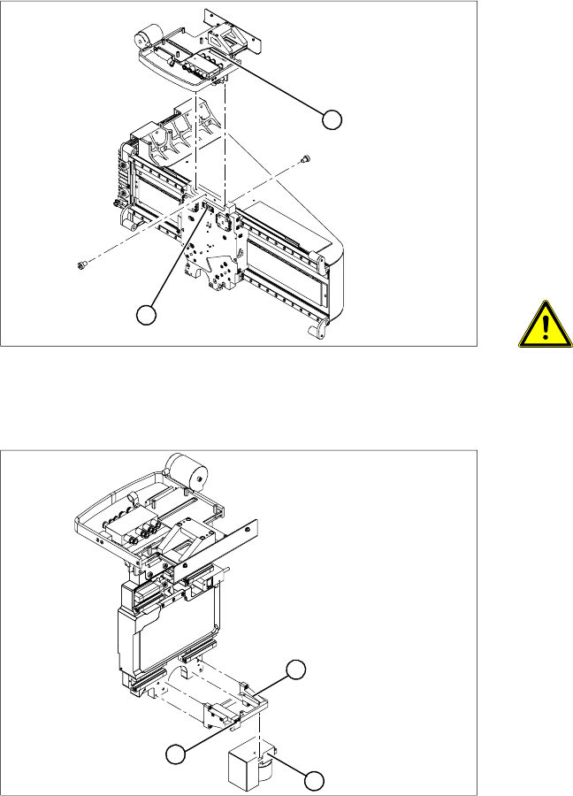
X Undo the 4 screws fastening the PCB camera
mount (1). Remove the complete unit,
including PCB camera (3) and damping
bracket (2).
X Remove the connection cable fixtures from the
gantry.
X For strain-relief purposes, fix the mount (1) to
a suitable place. Take care not to damage the
camera.
1
3
2