SIPLACE D系列Servicemanual.pdf - 第83页
Service Work D4 Gantry Servicemanual (internal version) SIPLACE D Series 83 4-22: Replacing the linear motor - primary part (1) Legend (1) Linear motor - primary part (4) Socket X4 for the connecting cable of the primary…
Service Work
Gantry D4
82 Servicemanual (internal version) SIPLACE D Series
X Lift the relevant permanent magnet and place it on a clean, nonmagnetic surface (such as a plank
of wood).
Make sure that any foreign parts or other magnets have been placed at a safe distance.
Installation
Settings
X Check the axis dynamics of the drives removed.
See also:
J
4.1.4.5 Replacing the X Motor Unit [00333167-03] [
J
86]
4.1.4.4 Replacing the Y Linear Motor - Primary Part [00333148-02]
Tools and Equipment
Set of DIN 911 Allen keys
Cable ties
Belt tension measuring device TSM [00326015-01]
"Measuring belt tensions" operating instructions
SITEST program
Parts
Linear motor - primary part [00333148-02]
Removing the primary part of the linear motor
X Fit the X axis motor unit as described in section (4.1.4.5 Replacing the X Motor Unit [00333167-03]
J
86 ) .
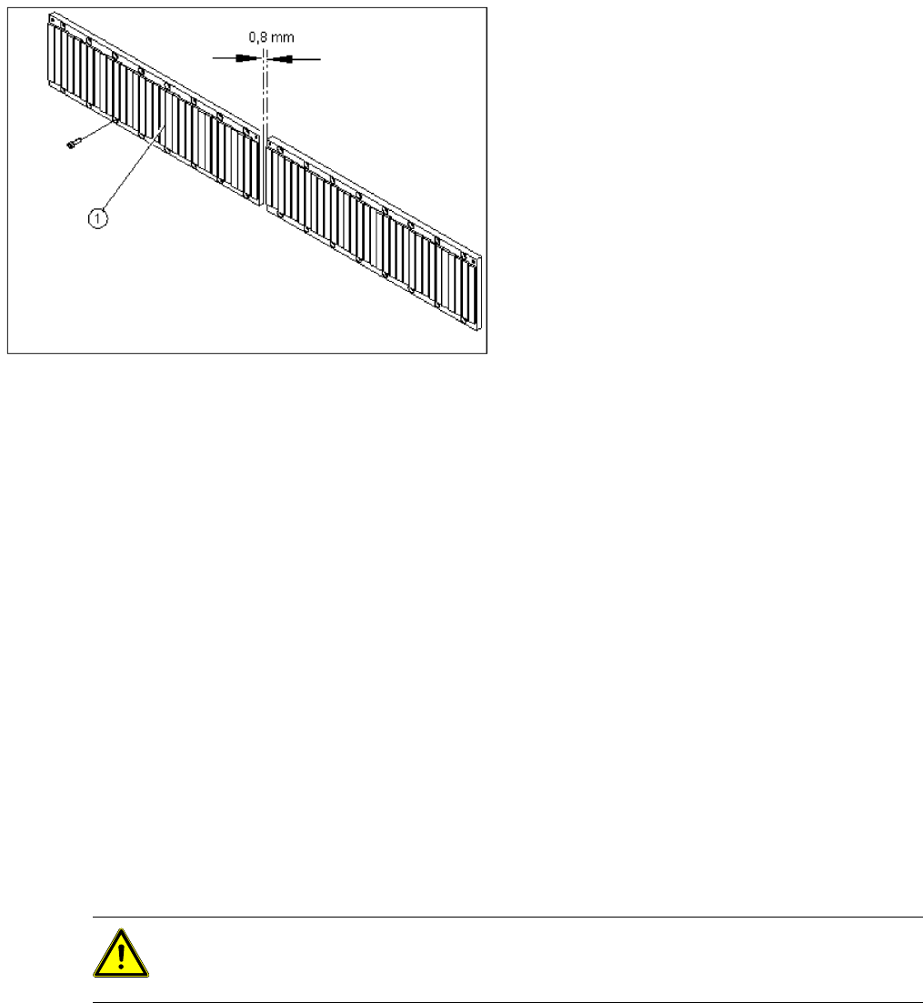
X Fit the permanent magnets (4 or 16 M6 x 12
hexagon socket-head screws). The space at
the bottom must be 0.8 mm. Use the
appropriate feeler gauge or plastic strip to help
you. A gap of approx. 0.8 mm should be
between the magnet plates.
X Fit the cover strips on the crossbeam above
the gantry concerned (3 M6 x 8 hexagon
socket-head screws).
CAUTION: Precondition
You must at least remove the magnetic strip behind the linear motor (see section (4.1.4.3 Re-
placing the Y Linear Motor - Secondary Part
J
80 ) ).
Service Work
D4 Gantry
Servicemanual (internal version) SIPLACE D Series
83
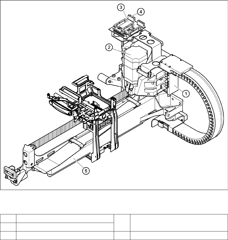
4-22: Replacing the linear motor - primary part (1)
Legend
(1) Linear motor - primary part (4) Socket X4 for the connecting cable of the
primary part
(1) X-axis motor unit
(5) X/Y distributor (5) Gantry
Service Work
Gantry D4
84 Servicemanual (internal version) SIPLACE D Series
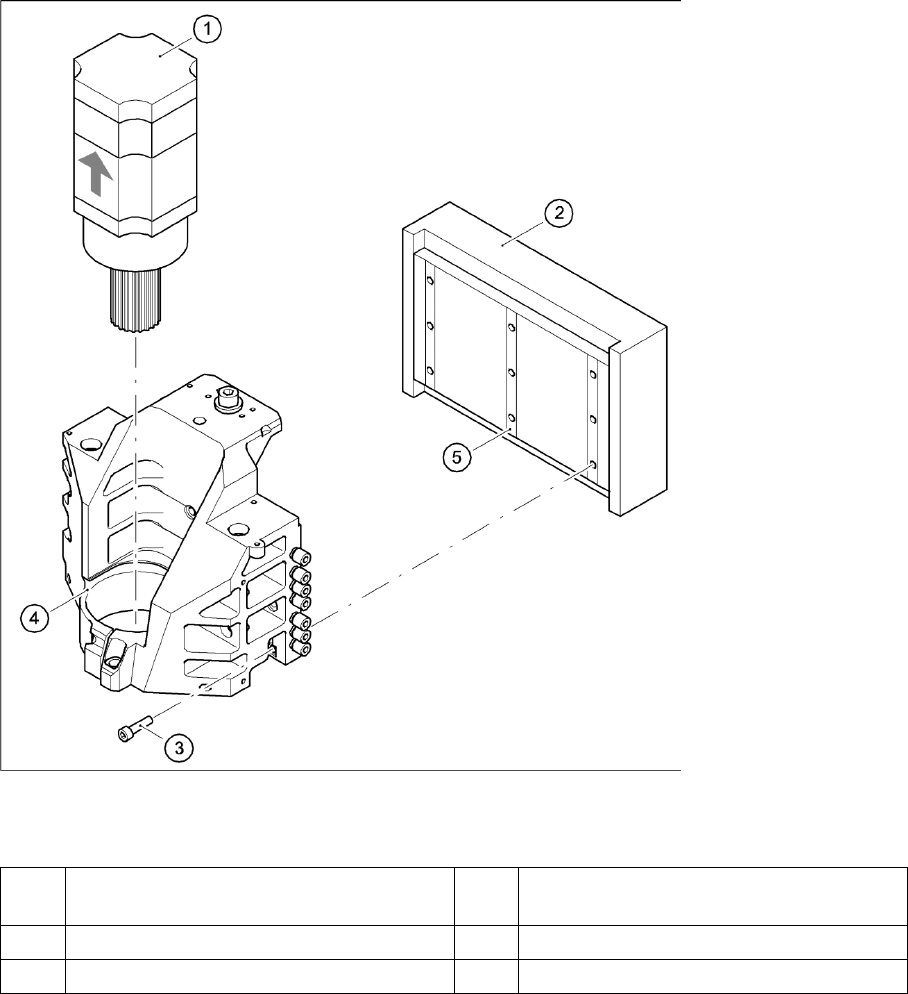
4-23: Replacing the linear motor - primary part (2)
Legend
X Loosen the nine M5 x 20 hexagon socket-head screws (3) and remove the primary part (2).
X Make sure that the lock rails will not drop.
(1) X-axis motor unit (4) Motor bracket with press-fit connection
(pneumatic system)
(1) Linear motor - primary part (5) Lockrail
(5) 9 x M5x20 hexagon socket-head screws