SIPLACE D系列Servicemanual.pdf - 第41页
Service Work D3 Gantry Servicemanual (internal version) SIPLACE D Series 41 Removing the scale X Place the new scale on a clean work surface. X Attach the double-sided adhe sive tape to the back of the new scale. The sur…
Service Work
Gantry D3
40 Servicemanual (internal version) SIPLACE D Series
4.1.3 D3
4.1.3.1 Replacing the X Axis Scale [03003745]
Special equipment
Scriber to loosen the scale
Ethanol
Protective gloves
Double-sided adhesive strip - Scotch Y-9460 [00343774-xx]
Protective sheet 12mm wide [00378511-xx]
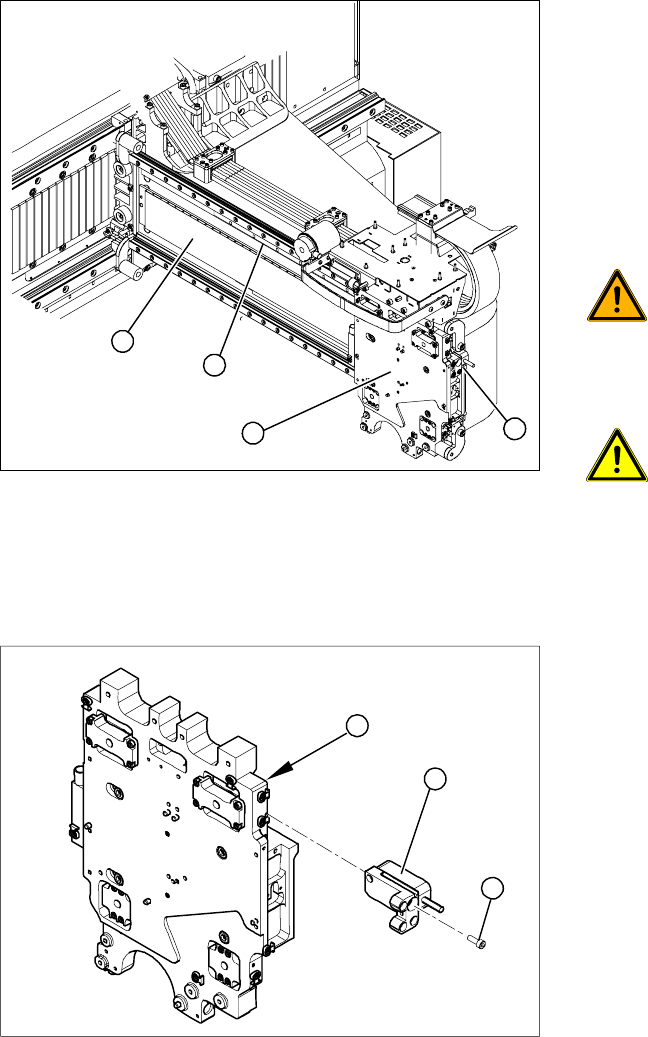
Overview
Removing the read head
Legend
1. Head plate
2. X axis scale (fixed with adhesive)
3. Permanent magnets
4. X axis read head
X Move the head plate (2) to a suitable position
so that you can easily access the X axis scale
(1) from all sides.
WARNING: STRONG MAGNETIC
FIELDS!
Always follow the special safety
instructions when working in the vicinity
of powerful magnetic fields, caused by
the permanent magnets (3).
ATTENTION: Do not dismantle the
head plate!
To guarantee accuracy, make sure that
you do not dismantle the head plate (2).
X Dismantle the read head (4).
4
1
3
2
Legend
1. Head plate - front view
2. Read head
3. 3 x fastening screws
X Loosen the three screws (3) fastening the read
head (2) of the X axis and carefully lift off the
read head.
X Temporarily fasten the read head in a suitable
position.
3
1
2
Service Work
D3 Gantry
Servicemanual (internal version) SIPLACE D Series
41
Removing the scale
X Place the new scale on a clean work surface.
X Attach the double-sided adhesive tape to the back of the new scale. The surface to be fixed down
must be clean and free of grease.
Installation of scale
X Insert the new scale behind the head plate.
X Attach the new scale exactly to the lay-on edge on the gantry.
X Pull part of the cover strip off the adhesive strip and place the front end of the scale on the marked
position. The scale must be positioned at the lay-on edge.
X Now pull away the cover strip „piece by piece“ and firmly fix the scale (to about halfway along the
gantry).
X Move the head plate so that you can fix the rest of the scale.
X Press the scale down with a soft, clean cloth.
X Carefully pull off the cover strip.
X Wipe a little ethanol over the scale to remove any adhesive residues or dirt.
X Fit the read head. This procedure is described in Chapter "Replacing the X Axis Read Head".
See also:
J
4.1.3.7 Replacing the X Axis Incremental Encoder [03020588S-xx] [
J
67]
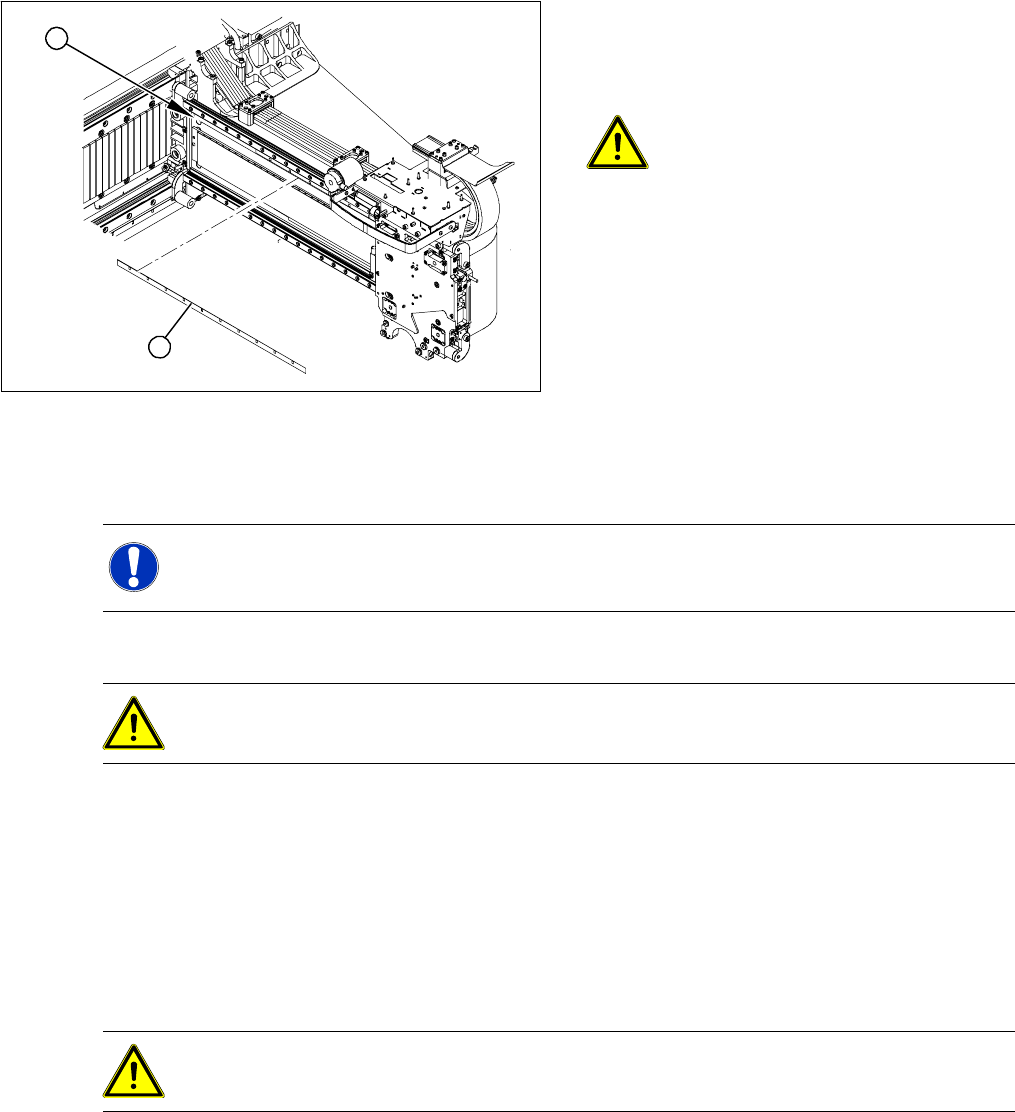
X Mark the original position (1) of the scale (2)
with a scribing iron. This ensures that the new
scale can be fixed in the exact position to the
right and left end stop.
ATTENTION: Do not damage the
gantry.
Make sure that the gantry coating is not
damaged.
X Carefully lever the scale upwards on one side
with the scriber and then gently extract the
scale.
X Remove any adhesive residues with ethanol.
The surface to be fixed down must be clean
and free of grease.
2
1
NOTE: Cover strip on scale
X A cover strip protects the front of the scale. Remove this cover strip AFTER installation.
ATTENTION: Take care when handling the incremental scale.
Do not touch the incremental tracks with bare fingers.
ATTENTION: Make sure that no blisters or uneven areas are formed.
If this does occur, the scale must be removed and replaced with a new scale.
Service Work
Gantry D3
42 Servicemanual (internal version) SIPLACE D Series
4.1.3.2 Replacing the Y Axis Scale [03005490]
Tools and equipment
Scale - adhesive device set (HF/ X Series) [00377013-xx]
Double-sided adhesive strip - Scotch Y-9460 [00343774-xx]
Protective sheet 12mm wide [00378511-xx]
Ethyl alcohol (provided with set)
Protective gloves (provided with set)
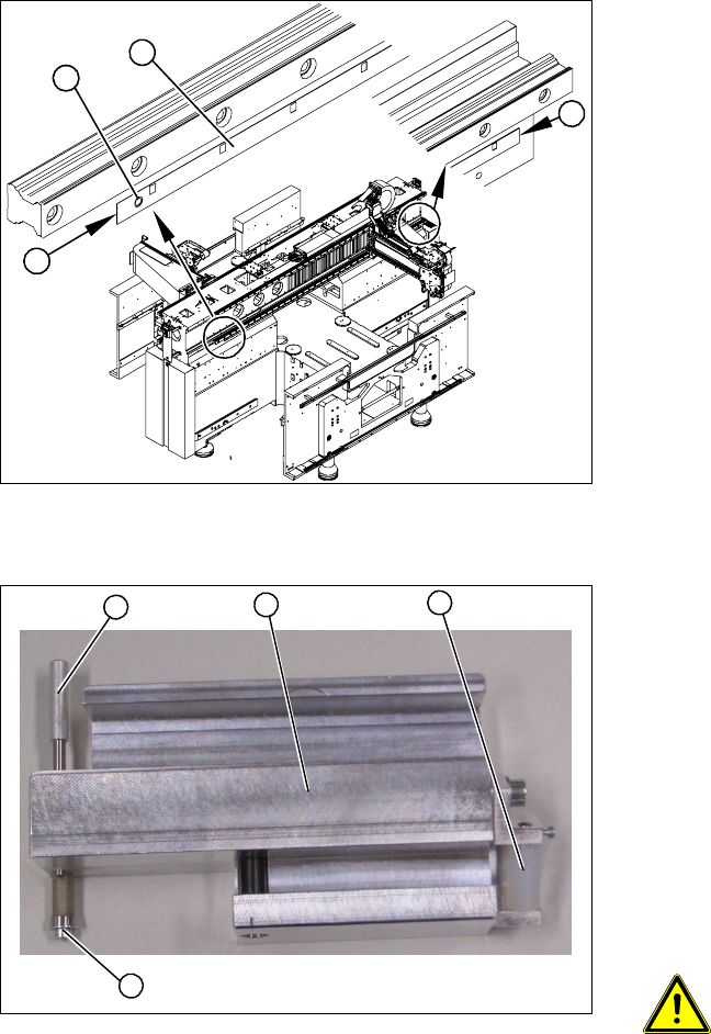
Prior checks
Checking the adhesive device
X Check whether there is a drill hole (1) on the
machine base. If not, you will need to mark the
start and end positions (2) of the old scale (3)
with a scribing iron.
X Check the length of the installed scale. If this is
shorter than the replacement scale, you will
need to fix the new scale from position 1 or 3
onwards with adhesive.
2
1
3
2
Legend
1. Press roller
2. Adhesive device (viewed from below)
3. Fixing pin
4. Screw
X Check the setting of the press roller (1).
X Place the adhesive device (2) and the press
roller flat onto the table.
X Place a plastic sheet (0.2 mm thickness) under
the press roller. Make sure that the press roller
lies flat on the plastic sheet.
ATTENTION: Set the fixing pin
correctly
The fixing pin for the scale must be set
so that it touches the screw (4) and can
guide the scale, without the latter
slipping out.
1
4
3
2