SIPLACE D系列Servicemanual.pdf - 第24页
Service Wo rk Gantry D1/D2 24 Servicemanual (internal ve rsion) SIPLACE D Series Removal 4-3: Adhesive device for scale Legend 1. Adhesive device for scale 2. Fastening screws 3. Scale guide Legend 1. X-axis scal e 2. X-…
Service Work
D1/D2 Gantry
Servicemanual (internal version) SIPLACE D Series
23
Before you begin work on site, use the following procedure to check whether all safety
measures are being observed:
Read the list of safety measures, whenever service work is required at the customer site:
X Download the applicable safety instructions or print them out and take them with you to the place of
work.
X Before you begin work, make sure that the required packaging materials (empty magnet packaging)
and any other materials required for the repairs/replacements are available.
X Before you begin work, go through the safety instructions with the other SIEMENS technicians
involved in the work.
X Begin the work.
4.1.2 D1/D2
4.1.2.1 Replacing the X Axis Scale [03003745]
Equipment required
Set for replacing the X scale [03055895-xx]:
– Adhesive device for scale (D1/D2) incl. 2 screws
– Double-sided adhesive strip
– Protective gloves
– Cleansing tissues
– Chisel
– Assembly guide
Set of Allen keys
Scribing iron
0.4 mm thickness gauge
Ethanol
System Task Required safety measures
HS, HF, X, D-series Replacing magnets Safety notes for removal/fitting the magnet
Document: EA-SD-001 (see above)
HS, HF, X, D-series Replacing gantries Safety notes for removal/fitting the magnet
Document: EA-SD-001 (see above)
HS, HF, X, D-series Y guide rail Safety notes for removal/fitting the magnet
Document: EA-SD-001 (see above)
HS, HF, X, D-series Replacing the Y motor Safety notes for removal/fitting the magnet
Document: EA-SD-001 (see above)
HS, X, D3 series Replacing the X motor Safety notes for removal/fitting the magnet
Document: EA-SD-001 (see above)
WARNING: STRONG MAGNETIC FIELDS!
Always follow the special safety instructions when working in the vicinity of powerful magnetic
fields, caused by the permanent magnets.
ATTENTION:
Make sure that you do not scratch or bend the scale!
Service Work
Gantry D1/D2
24 Servicemanual (internal version) SIPLACE D Series
Removal
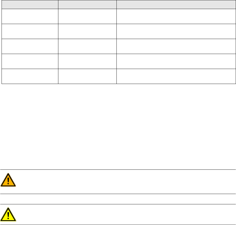
4-3: Adhesive device for scale
Legend
1. Adhesive device for scale
2. Fastening screws
3. Scale guide
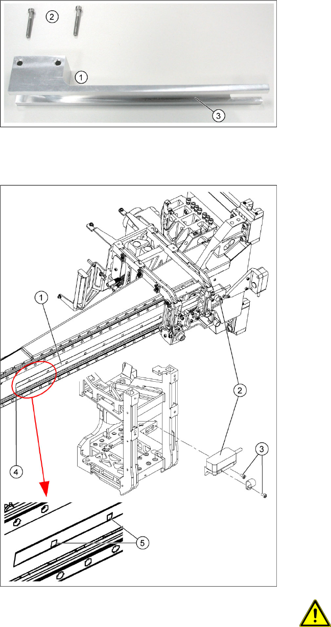
Legend
1. X-axis scale
2. X-axis incremental encoder (read head)
3. Fastening screws for incremental encoder
4. Starting position of scale
5. Zero pulse on scale
X Move the relevant changeover table out of the
machine.
X Switch off the machine.
X Move the gantry into the position which allows
you best access.
X Loosen the two screws (3) fastening the
incremental encoder (2). Let the encoder
dangle down below the gantry, from its cable.
X Use a scribing iron to mark the starting position
(4) of the scale, near the deflection unit,
opposite the X motor.
X Wear protective gloves.
X Use the chisel to lever the old scale (1) off the
machine frame and then remove the scale.
X Clean the contact surface with a cleansing
tissue and ethanol, to remove any remaining
adhesive. The contact surface must be clean
and free of grease. If you are unable to
achieve this with the cleansing tissue alone,
use the chisel to help you.
ATTENTION:
Make sure that you do not scratch the
contact surface!
Service Work
D1/D2 Gantry
Servicemanual (internal version) SIPLACE D Series
25
Installation
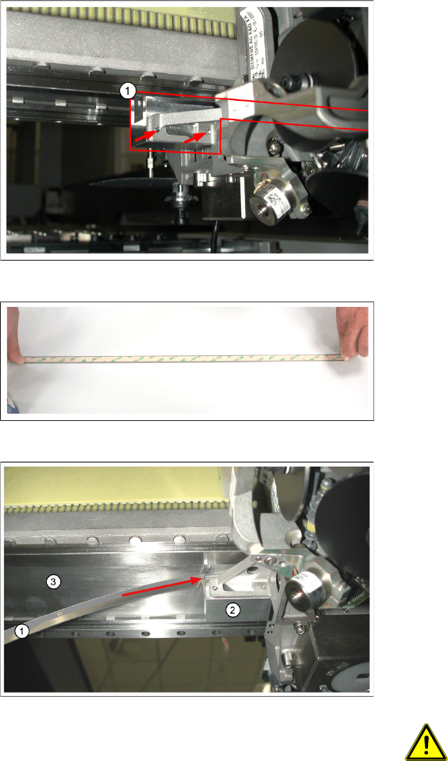
Legend
1. Adhesive device, fitted at the gantry (not fully
visible)
X Fit the adhesive device at the gantry, in place
of the incremental encoder. To do this, thread
the long, thin part of the adhesive device in
under the head mount, so that this long, thin
part is pointing towards the deflection unit.
X Press the adhesive device up, against the
gantry, and fix it in place with the two screws
provided ((arrows) – the picture only shows
the ends of the screws).
X Place the new scale on a clean work surface.
X Clean the back of the scale with the cleaning
agent provided. The surface to be fixed down
must be clean and free of grease.
X Attach the double-sided adhesive tape to the
back of the new scale.
Legend
1. Scale
2. Adhesive device
3. Adhesive surface on the underside of the
gantry
X Remove the protective cover from the
adhesive strip on the back of the scale.
X Thread the scale into the adhesive device
(arrow). Make sure that the scale does not yet
remain sticking to the adhesive surface on the
underside of the gantry.
ATTENTION: Aligning the scale
When viewed in the direction of
transport, the zero pulses must be on
the left side of the gantry i.e. aligned
towards the C&P head. You can also
use the zero pulse window of the scan
head for orientation.