SIPLACE D系列Servicemanual.pdf - 第88页
Service Wo rk Gantry D4 88 Servicemanual (internal ve rsion) SIPLACE D Series Installing the X-axis motor unit 4-27: Replacing the X-axis motor unit Gantry 1 or 3 X Carefully insert the X motor unit (4) as far as the sto…

Service Work
D4 Gantry
Servicemanual (internal version) SIPLACE D Series
87
Gantry 1 or 3
X Remove the black cover strip on the cross-beam above the gantry concerned:
Unplug the fan cable. The fan is fixed to the black cover strip.
Remove the black cover strip (3 M6x8 hexagon socket-head screws).
X Cut the cable ties holding the X-axis motor cable.
X Remove the cable clamp for the flat ribbon cable (11).
X Disconnect all the plugs from the X/Y distributor (5).
X Remove the X/Y distributor (5).
X Remove the board holder for the X/Y distributor (9).
X Remove the cable holders (10) on the trailing cable.
X To relax the toothed belt (3), proceed as follows:
Loosen the locknut (8),
Turn the hexagon socket-head screw (2) counterclockwise.
X Loosen the two M6 x14 hexagon socket-head screws (7) fixing the X motor unit (4).
X Pull the X motor unit (4) up and out,
X at the same time pushing the board holder slightly to the side.
Gantry 2 or 4
X Remove the black cover strip on the cross-beam above the gantry concerned:
Unplug the fan cable. The fan is fixed to the black cover strip.
Remove the black cover strip (3 M6x8 hexagon socket-head screws).
X Cut the cable ties holding the X-axis motor cable.
X Remove the cable clamp for the flat ribbon cable (11).
X Disconnect all the X motor plugs from the X/Y distributor (5).
X Remove the board holder for the X/Y distributor (9).
X Remove the cable holders (10) on the trailing cable.
X To relax the toothed belt (9), proceed as follows:
Loosen the locknut (8),
Turn the hexagon socket-head screw (2) counterclockwise.
X Loosen the two M6 x14 hexagon socket-head screws (7) fixing the X motor unit (4).
X Pull the X motor unit (4) up and out,
at the same time pushing the board holder slightly to the side.
DANGER: POWERFUL MAGNETIC FIELD
X Always follow the special safety instructions when working in the vicinity of powerful magnetic
fields.
Service Work
Gantry D4
88 Servicemanual (internal version) SIPLACE D Series
Installing the X-axis motor unit
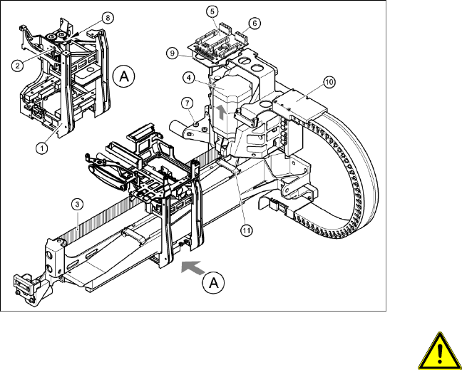
4-27: Replacing the X-axis motor unit
Gantry 1 or 3
X Carefully insert the X motor unit (4) as far as
the stop,
making sure that you do not damage the
toothed belt. The motor cable points towards
the permanent magnets of the linear drive.
X Fix the X motor unit into place with the two
hexagon socket-head screws (7).
X Fit the cable holders for the trailing cable (10).
X Fit the board holder (9).
X Fit the X/Y distributor (5).
X Connect all plugs to their sockets on the X/Y
distributor (5).
X Fix the flat ribbon cable with the cable clamp
(11).
X Fix all the cables with cable ties.
CAUTION:
Make sure that the cables are firmly
seated. Otherwise, the high
acceleration forces may cause the
cable to slip out of position and shear
through.
X Tension the X toothed belt with the hexagon
socket-head screw (2).
X Use the three M6 x 8 hexagon socket-head
screws to fit the black cover strip to the
crossbeam above the gantry concerned.
X Connect the cable of the fan motor to the
socket.
Service Work
D4 Gantry
Servicemanual (internal version) SIPLACE D Series
89
Settings
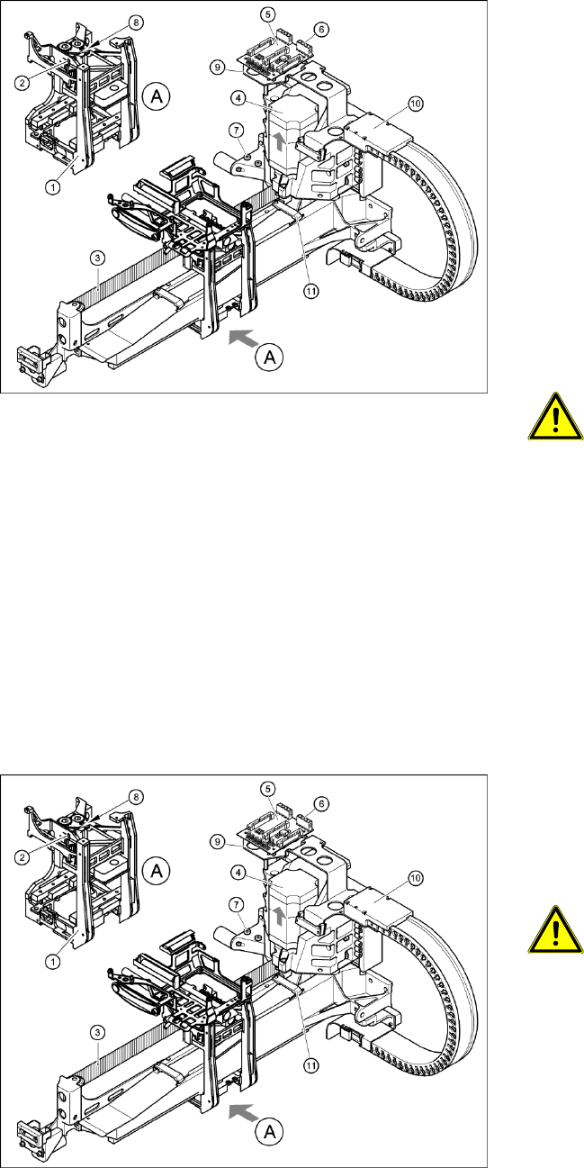
4-28: Replacing the X-axis motor unit
Gantry 2 or 4
X Carefully insert the X motor unit (4) as far as
the stop, making sure that you do not damage
the toothed belt. The motor cable points
towards the permanent magnets of the linear
drive.
X Fix the X motor unit into place with the two
hexagon socket-head screws (7).
X Fit the cable holders for the trailing cable (10).
X Fit the board holder (9).
X Plug the X motor plug into its socket on the X/
Y distributor (5).
X Fix the flat ribbon cable with the cable clamp
(11).
X Fix all the cables with cable ties.
CAUTION:
Make sure that the cables are firmly
seated. Otherwise, the high
acceleration forces may cause the
cable to slip out of position and shear
through.
X Tension the X toothed belt with the hexagon
socket-head screw (2).
X Use the three M6 x 8 hexagon socket-head
screws to fit the black cover strip to the
crossbeam above the gantry concerned.
X Connect the cable of the fan motor to the
socket.
4-29: Replacing the X-axis motor unit
X Push the head mount (1) towards the X axis
motor unit, as far as the stop on the
elastomeric spring.
X Turn the hexagon socket-head screw (2) to set
the belt tension to 53 Hz + 1/-3 Hz.
CAUTION:
Do not overstretch the toothed belt
when adjusting the belt tension.
X Secure the hexagon socket-head screw (2)
with the locknut (8).