00192975-01.pdf - 第110页
Power supply S-20/S-23HM/F4/F5/F5H M/S-25HM/HS-50 Conversion Instruct ions 4.4 Converting the power supply from 3 x 400 VA C to 3 x 204 V ~ 03/2001 E dition 110 4.4 Converting the power supply from 3 x 400 V AC to 3 x 20…
S-20/S-23HM/F4/F5/F5HM/S-25HM/HS-50 Conversion Instructions Power supply
03/2001 Edition 4 Converting the power supply unit on HS-50 placement machines
109
4.2 Tools and equipment
– Set of DIN 911 Allen keys
– Set of slotted-head screwdrivers
– Multimeter
4.3 Parts
4.3.1 110/204 V conversion kit for SIPLACE HS-50,
article no. 00119085-01
The conversion kit consists of the following parts:
– ZM-32-PKZ2 motor protection trip block Article number 00342496-01
– HS-50 cable: machine power supply (USA), Article number 00345937-01
– Socket with earthing contact 15 A, 125 VAC Article number 00346283-01
– Circuit diagram, 110/208 V conversion kit for SIPLACE HS-50
drawing no. 00119085-010101FD4
– Circuit diagram, 110/208 V conversion kit for SIPLACE HS-50
drawing no. 00119085-010101LD4
– Power supply conversion instructions
for SIPLACE S-20/S-23HM/S-25HM/F
4
/F
5
/F5HM/HS-50 Article number. 00191498-01
03/2001 issue, German and English
for SIPLACE
4.3.2 International (3x400 VAC) conversion kit for SIPLACE HS-50
article no. 00119185-01
The conversion kit consists of the following parts:
– ZM-16-PKZ2 motor protection trip block Article number 00342495-01
– Circuit diagram, conversion kit for SIPLACE HS-50, international
drawing no. 00119185-010101FD4
– Circuit diagram, conversion kit for SIPLACE HS-50, international
drawing no. 00119185-010101LD4
– Power supply conversion instructions
for SIPLACE S-20/S-23HM/S-25HM/F
4
/F
5
/F5HM/HS-50 Article number. 00191498-01
03/2001 issue, German and English
for SIPLACE
Power supply S-20/S-23HM/F4/F5/F5HM/S-25HM/HS-50 Conversion Instructions
4.4 Converting the power supply from 3 x 400 VAC to 3 x 204 V ~ 03/2001 Edition
110
4.4 Converting the power supply from 3 x 400 VAC to 3 x 204 V ~
RISK OF DEATH 4
Å Disconnect the machine correctly as described in section 1, page 71.
Å Disconnect the machine from the main power supply.
Å Take suitable action to ensure that the machine cannot be connected to the power supply
during the conversion work.
Å Put up warning signs to indicate that work is being carried out on the electrical system.
4.4.1 Removing the power supply unit
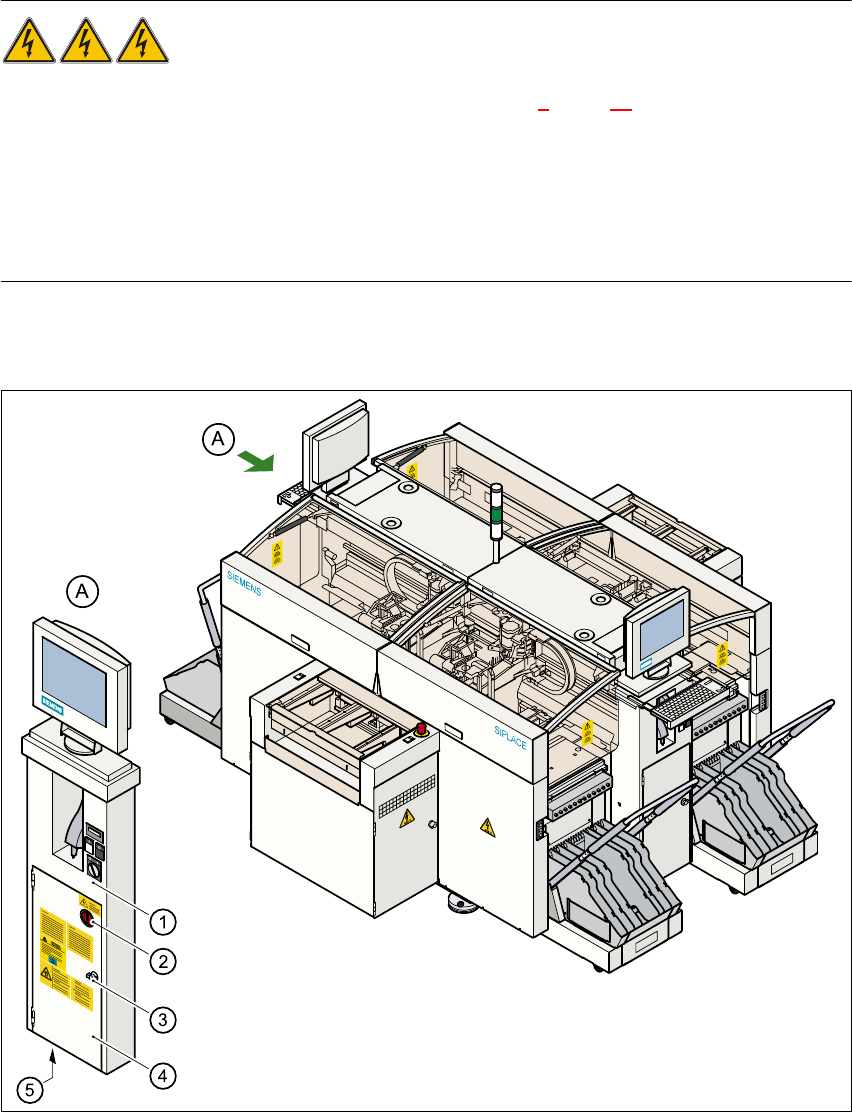
Fig. 4 - 1 Accessing the power supply unit
4

S-20/S-23HM/F4/F5/F5HM/S-25HM/HS-50 Conversion Instructions Power supply
03/2001 Edition 4 Converting the power supply unit on HS-50 placement machines
111
a 2SHUDWRUSDQHOOHIWKDQGVLGH
s 0DLQVZLWFK
d 'RRUORFN
f 3URWHFWLYHGRRUVWRSRZHUVXSSO\XQLW
g +ROHIRUSRZHUFDEOH
Å Open the lock (item d in Fig. 4 - 1) on the protective doors (item f in Fig. 4 - 1 using the two-
way key.
Å Use the Allen key to loosen the M8 locking screw (item M8 in Fig. 4 - 2) on the lower front panel.
Å Pull the power supply unit out as far as the stop.