00192975-01.pdf - 第127页
S-20/S-23HM/F4/F5/F 5HM/S-25HM/HS- 50 Conversion Instructions Power supply 03/2001 Edition 4 Converting the power supply unit on HS-50 placement m achines 127 4.5.6 Carry out the safety check to DIN EN 60 204 Å W hen the…
Power supply S-20/S-23HM/F4/F5/F5HM/S-25HM/HS-50 Conversion Instructions
4.5 Converting the power supply from 3 x 204 VAC to 3 x 400 V ~ 03/2001 Edition
126
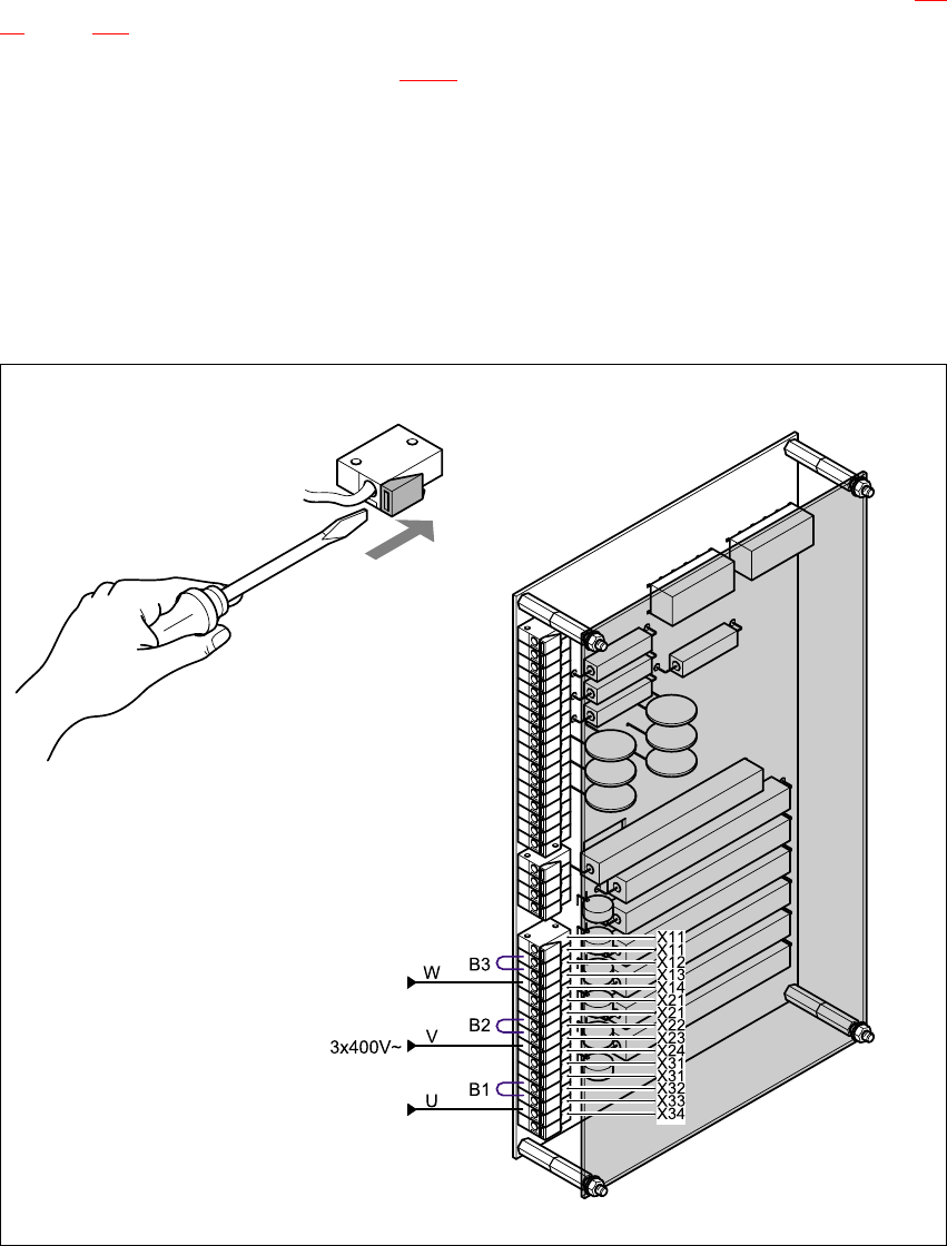
4.5.5 Reconnecting the inrush current limiter board
The inrush current limiter board is located on the back of the front panel (see item EST in Fig. 4 -
18, page 125.
Å Move the following jumpers (see Fig. 4 - 20):
B3 from terminal X13 to terminal X12
B2 from terminal X23 to terminal X22 and
B1 from terminal X33 to terminal X32.
Å Reconnect the following wires:
(W) from terminal X14 to terminal X13,
(V) from terminal X24 to terminal X23 and
(U) from terminal X34 to terminal X33.
)
:
Fig. 4 - 20 Reconnecting the inrush current limiter board

S-20/S-23HM/F4/F5/F5HM/S-25HM/HS-50 Conversion Instructions Power supply
03/2001 Edition 4 Converting the power supply unit on HS-50 placement machines
127
4.5.6 Carry out the safety check to DIN EN 60 204
Å When the conversion is complete, carry out a safety check to DIN EN 60 204.
Å Follow the procedure described in section 2, page 72 onwards.
Power supply S-20/S-23HM/F4/F5/F5HM/S-25HM/HS-50 Conversion Instructions
4.6 HS-50 circuit diagrams 03/2001 Edition
128
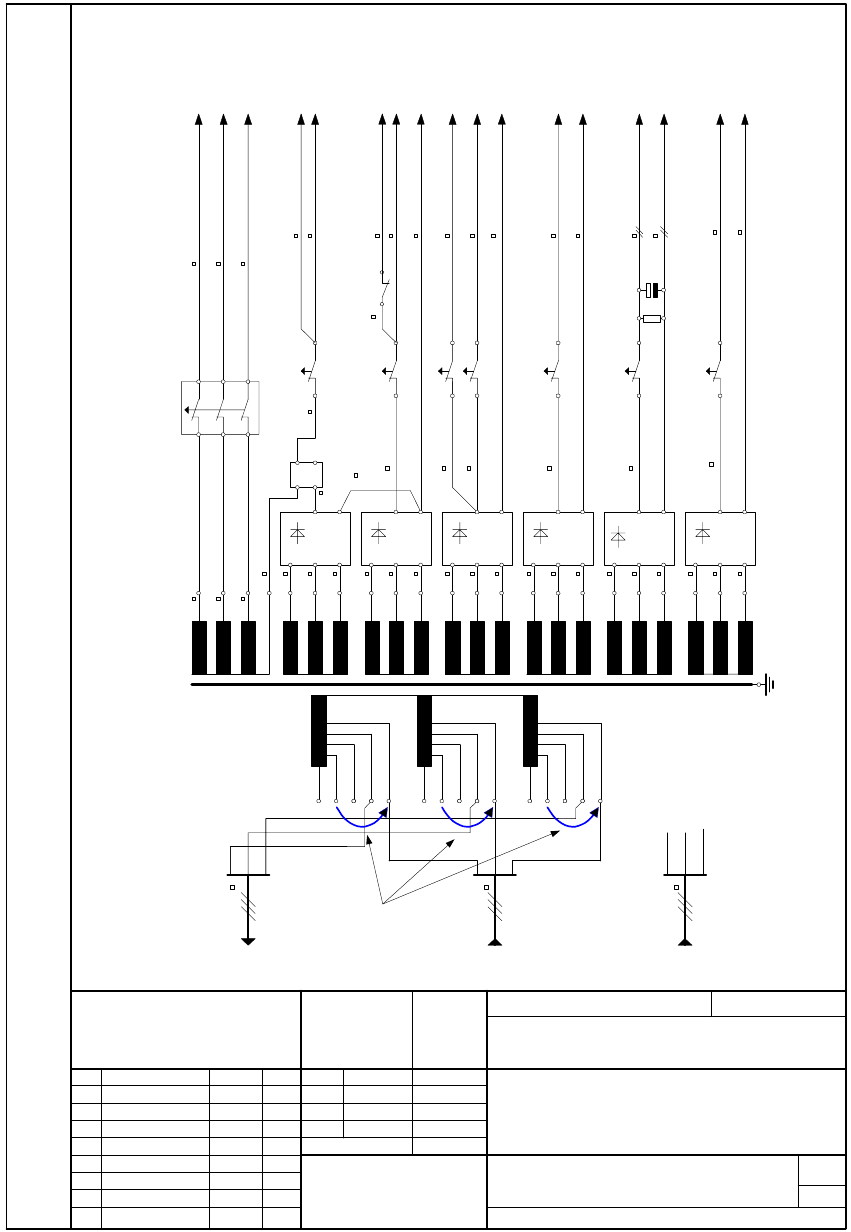
4.6 HS-50 circuit diagrams
01.
05.02.99
Tek
20.04.01
SMD Placement System SIPLACE HS50
110/208V Conversion kit
00119085-010101LD4
SIEMENS
Aktiengesellschaft
PL EA 1 E2
Date
Author
Check.
Stand.
Name
Stat. Modified Datum Name
(Drawing number)
Format A4
Sheet
Scale
Weitergabe sowie Vervielfältigung dieser Unterlage, Verwertung und Mitteilung
ihres Inhaltes nicht gestattet, soweit nicht ausdrücklich zugestanden.
Zuwiderhandlungen verpflichten zu Schadenersatz. Alle Rechte für den Fall
der Patenterteilung oder GM-Eintragung vorbehalten.
Copying of this document, and giving it to others and the use or communication
of the contents thereof, are forbidden without express authority. Offenders are
liable to the payment of damages. All rights are reserved in the event of the
grant of a patent or the registration of the utility model or design.
Function status
Product status
Document status
Sh.
Material no. - FS ES US UA/S/F
Berger
12.01.1999
2
for SIPLACE HS50 ( for the USA )
01.
01.
Tek
Tek
12.01.99
12.01.99
1
1U1 415V
1U3 400V
1U4 380V
Grounding terminal
Machine supply
system
(Sheet 3)
PCB handling
∼
∼
∼
+
−
∼
∼
∼
+
−
∼
∼
∼
+
−
∼
∼
∼
+
−
∼
∼
∼−
F4
U_XY
V_XY
W_XY
Z/D servo
Star servo
DC/DC converter
P100P6V
P30V
(Sheet 5)
N
3
0
V
P48V
(Sheet 5)
N48V
+
P
8
V
(Sheet 5)
N8V
CO table
P34V
(Sheet 4/5)
1
P
3
4
V
(Sheet 5)
CO table
25
A
6
A
10
A
10
A
10
A
10
A
140V
39.4V
7.9V
31.5V
23.8V
4.0V
(Sheet 5)
33 000µF
+
−
∼
∼
D32A
T1
V
3
V
4
V
5
V
6
V
7
F5
F6
F7
F8
F9
F10
C1
V
2
4
1.5
1.5
1.5
1.5
1.5
1.5
1.5
1.5
1.5
1.5
1.5
1.5
1.5
2.5
2.5
2.5
1.5
1.5
1.5
1.5
1.5
1.5
1.5
1.5
2.5
2.5
R1
N34V
(Sheet 5)
6
6
6
6
6
6
P100P6V_R
(Sheet 2b)
12K12
SZ1
P30V_R
(Sheet 2b)
1.5
1.5
Discharge resistor
Discharge resistor
1.5
1.5
1.5
1.5
1.5
1.5
1.5
2.5
1.5
22k
Ω
1U6 204V
1U5 230V
∼
∼
∼
+
−
Psz1
(Sheet 1)
Nsz1
1
A
23.8V
V
8
F11
1.5
1.5
1.5
0.75
0.75
0.75
Transformer
primary
(Sheet 1)
4
(Sheet 1)
4
1V1 415V
1V3 400V
1V4 380V
1V5 230V
1V6 204V
1W6 204V
1W5 230V
1W4 380V
1W3 400V
1W1 415V
1U3 400V
1V3 400V
1W3 400V
⇐
⇐
⇐
1U6 204V
1V6 204V
1W6 204V
1U3 400V
Change
connections
Transformer
primary