00192975-01.pdf - 第93页
S-20/S-23HM/F4/F5/F 5HM/S-25HM/HS- 50 Conversion Instructions Power supply 03/2001 Edition 3 Converting the power supply on S-20/S-23HM/ S-25HM/F4/F5 and F5HM machines 93 3.8 Converting placeme nt machines from 3 x 208 V…
Power supply S-20/S-23HM/F4/F5/F5HM/S-25HM/HS-50 Conversion Instructions
3.7 Converting the wafflepack changer from 3x400 VAC to 3x230 VAC 03/2001 Edition
92
Å Remove the two jumpers between terminals 1U2 - 1V2 and 1V2 - 1W2.
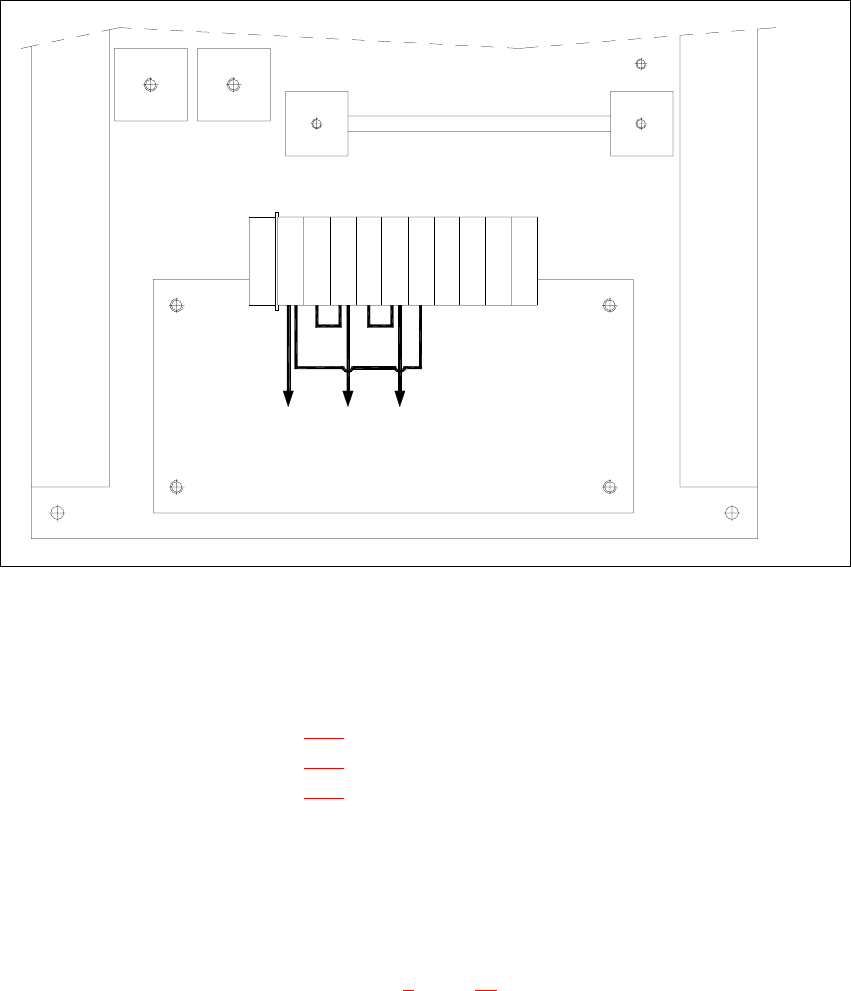
Fig. 3 - 8 Wafflepack changer, transformer T1, connection: 3 x 230 VAC
3
Å Place the three jumpers between the following terminals:
1U1 → 1W2 BR5 (see Fig. 3 - 8
)
1U2 → 1V1 BR7 (see Fig. 3 - 8
)
1V2 → 1W1 BR6 (see Fig. 3 - 8
)
Å Finally, attach the cover plate to the rear panel of the wafflepack changer.
3.7.2 Carry out the safety check to DIN EN 60 204
Å When the conversion is complete, carry out a safety check to DIN EN 60 204.
Å Follow the procedure described in section 2, page 72 onwards.
Terminals
G1
G2
PE
T1
transformer
PE 1U11U2 1V1 1V21W11W2 65 65 65 N
3 x 230 VAC
BR5BR6BR7

S-20/S-23HM/F4/F5/F5HM/S-25HM/HS-50 Conversion Instructions Power supply
03/2001 Edition 3 Converting the power supply on S-20/S-23HM/ S-25HM/F4/F5 and F5HM machines
93
3.8 Converting placement machines from 3x208V~ to 3x400V~
PLEASE NOTE: 3
Uncouple the two changeover tables before switching off the machine.
The wafflepack changer can remain coupled to the machine during conversion. 3
RISK OF DEATH 3
Å Disconnect the machine correctly as described in section 1, page 71.
Å Disconnect the machine from the main power supply.
Å Take suitable action to ensure that the machine cannot be connected to the power supply
during the conversion work.
Å Put up warning signs to indicate that work is being carried out on the electrical system.
Power supply S-20/S-23HM/F4/F5/F5HM/S-25HM/HS-50 Conversion Instructions
3.8 Converting placement machines from 3x208V~ to 3x400V~ 03/2001 Edition
94
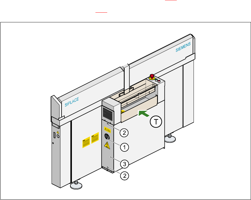
3.8.1 Removing the power supply unit
Å Loosen the two hexagon socket head screws (item 2 in Fig. 3 - 9).
Å Remove the cover (item 3 in Fig. 3 - 9).
Fig. 3 - 9 Removing the cover over the power supply unit
a 0DLQVZLWFK
s +H[DJRQVRFNHWKHDGVFUHZ[
d &RYHU
(T) PCB transport direction 3
Å Loosen the hexagon socket-head screw at the bottom of the power supply unit.
Å Take hold of the handle and remove the power supply unit from the housing.
The terminals on transformers T1 and T2 and the inrush current limiter can now be accessed
for rewiring.