00192975-01.pdf - 第74页
Power supply S-20/S-23HM/F4/F5/F5H M/S-25HM/HS-50 Conversion Instruct ions 2.2 Testing equipment 03/2001 Edition 74 T wo differen t versions of the distri butor box may be use d to co nnect the t estin g devi ce: 2 a &ap…
S-20/S-23HM/F4/F5/F5HM/S-25HM/HS-50 Conversion Instructions Power supply
03/2001 Edition 2 Safety check to DIN EN 60 204
73
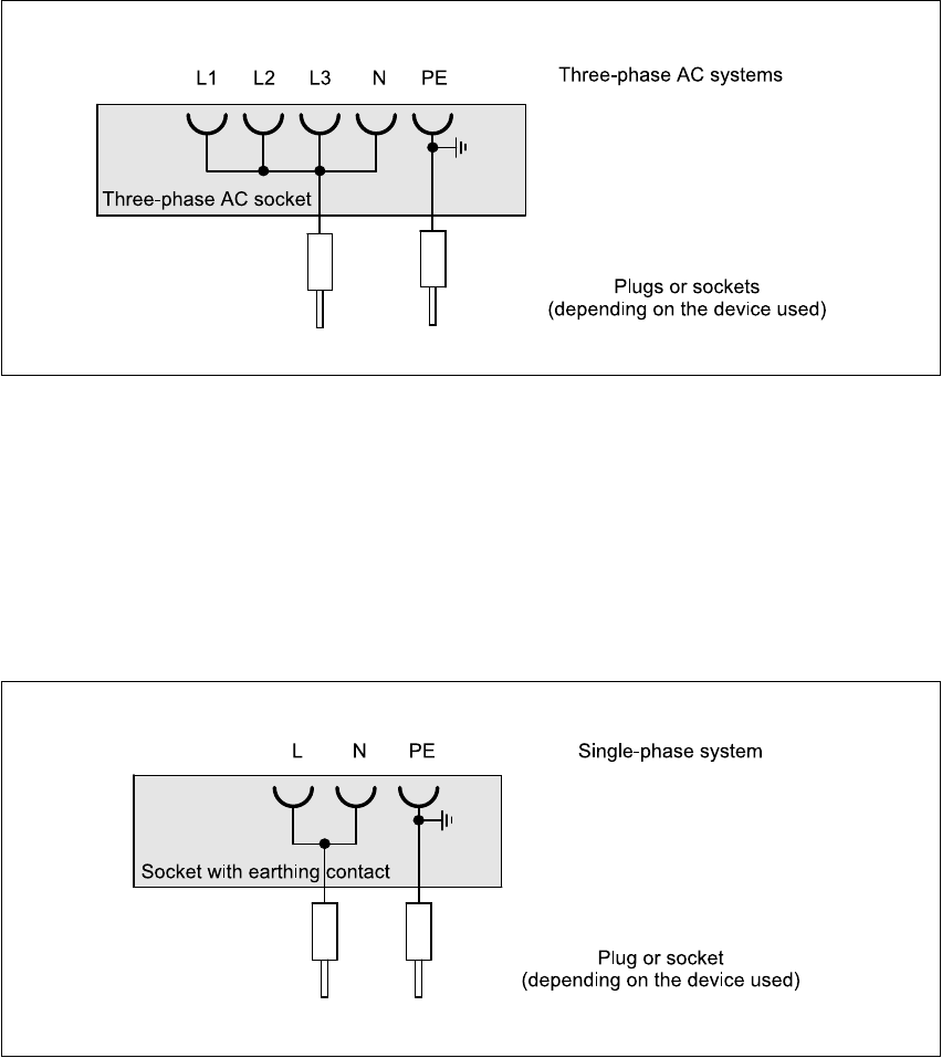
testing device in the distributor box. The ends of the cables may be plugs or sockets, depending
on the type of connection. 2
Fig. 2 - 1 Three-phase AC socket for the insulation and high-voltage test
2.2.2 Socket with earthing contact and connecting cable for the insulation and
high-voltage test
For the insulation and high-voltage tests, you will need a socket with earthing contact and a
connecting cable as shown in the following drawing. This is used to electrically connect the test
piece to the testing device in the distributor box. The ends of the cable may be
plugs or sockets, depending on the type of connection. 2
Fig. 2 - 2 Socket with earthing contact for the insulation and high-voltage test
2.2.3 Distribution box for the insulation and high-voltage test
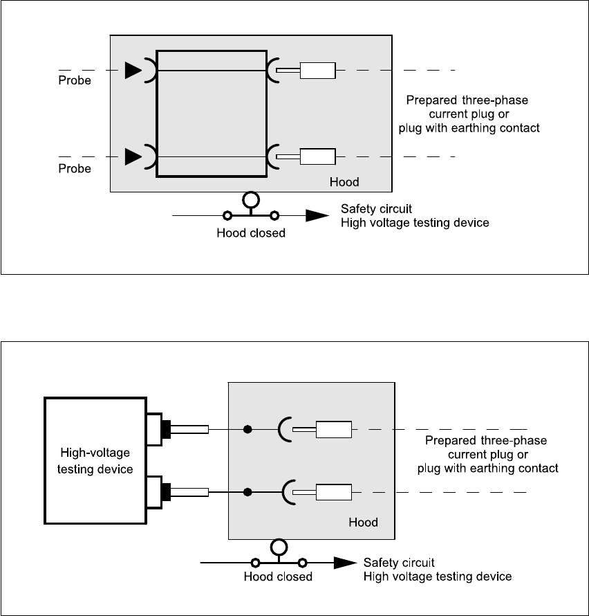
A distributor box with protective hood is required for the electrical connection between the test
device and test piece. When the protective hood is closed, the circuit-breaker in the distributor box
closes the safety circuit of the testing device. If the protective hood is opened, the protective hood
switch interrupts the safety circuit, immediately disconnecting the high voltage used for the test. 2
Power supply S-20/S-23HM/F4/F5/F5HM/S-25HM/HS-50 Conversion Instructions
2.2 Testing equipment 03/2001 Edition
74
Two different versions of the distributor box may be used to connect the testing device: 2
a 'LVWULEXWRUER[IRUFRQQHFWLQJWKHSUREHVRIWKHWHVWLQJGHYLFH
Fig. 2 - 3 Distributor box for connecting the probes of a testing device
s 'LVWULEXWRUER[ZLWKIL[HGFRQQHFWLQJFDEOHVWRWKHWHVWLQJGHYLFH
Fig. 2 - 4 Distributor box for connecting fixed connecting cables to the testing device

S-20/S-23HM/F4/F5/F5HM/S-25HM/HS-50 Conversion Instructions Power supply
03/2001 Edition 2 Safety check to DIN EN 60 204
75
2.3 Insulation test
2.3.1 Permissible minimum insulation resistance
The insulation resistance is measured at 500 VDC between the conductors of the main power
circuits and the protective earth conductors. 2
The permissible minimum insulation resistance is > 1.3 MOhm. 2
PLEASE NOTE:
All the electrical connections must be fully installed on the machine, including those for the power
supply. 2
2.3.2 Insulation testers
2.3.3 Performing the insulation test
Å Create a test set-up as illustrated in figure 2 - 5.
Å Follow the instructions in the manual for the testing device.
Å Measure the insulation resistance at 500 VDC.
Å Enter the measured value into the test report.
If the measured value is > 1.3 MOhm, the machine has passed the insulation test and can be
released. If the measured value is smaller, the error must be eliminated and the test repeated.
Available testers
• SIEMENS insulation meter M05835-A2/2173984
•ELECTROTECHNICAL LABORATORY, KORNTAL RD28K safety tester
• GOSSEN-METRAWATT 204P (0.05 - 50 MOhm)
• METRAMACHINE 204 (compete system for tests to VDE0113) consisting
of Profikit 204, Profitest 204 HP, Signal 204, Leadex 204 and Caddy 204
Measuring range 0.4 - 10 MOhm
Measuring voltage 500 VDC
Tab. 2 - 1 Insulation testers