00192975-01.pdf - 第97页
S-20/S-23HM/F4/F5/F 5HM/S-25HM/HS- 50 Conversion Instructions Power supply 03/2001 Edition 3 Converting the power supply on S-20/S-23HM/ S-25HM/F4/F5 and F5HM machines 97 Fig. 3 - 1 1 Front panel of the power supply unit…

Power supply S-20/S-23HM/F4/F5/F5HM/S-25HM/HS-50 Conversion Instructions
3.8 Converting placement machines from 3x208V~ to 3x400V~ 03/2001 Edition
96
3.8.2 Converting the single-phase transformer T1 from 110 VAC to 230 VAC
Å Detach the black connecting wire from terminal f (110 V) and connect it to terminal h (230 V)
see Fig. 3 - 10
).
3.8.3 Converting the three-phase transformer T2 from 3 x 208 VAC to 3 x 400 VAC
Å Detach the black connecting wire from terminal j (208 V) and connect it to terminal a (400 V)
see Fig. 3 - 10
).
Å Detach the black connecting wire from terminal k (208 V) and connect it to terminal s (400 V)
see Fig. 3 - 10
).
Å Detach the black connecting wire from terminal l (208 V) and connect it to terminal d (400 V)
see Fig. 3 - 10
).
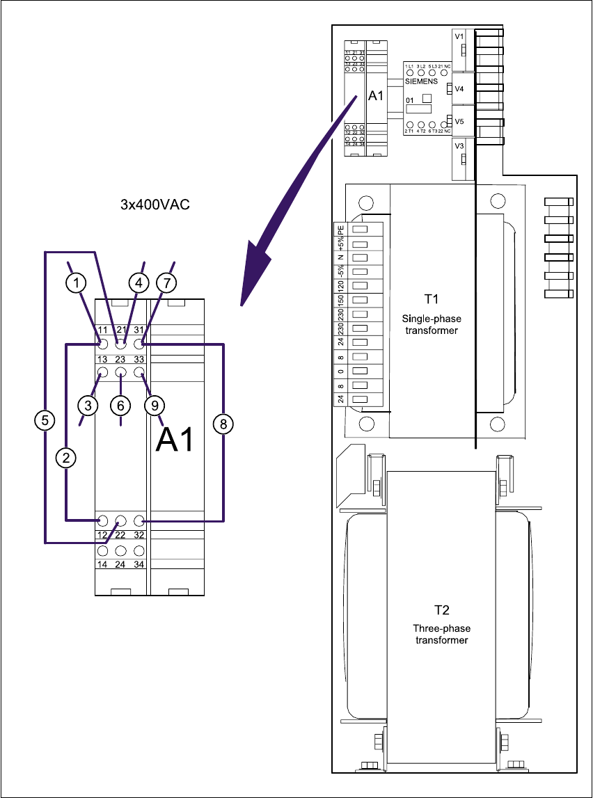
3.8.4 Converting the inrush current limiter A1 from 3x400 VAC to 3x208 VAC
Å Detach wire d from terminal 14 and connect to terminal 13 (see Fig. 3 - 11).
Å Detach wire h from terminal 24 and connect to terminal 23 (see Fig. 3 - 11).
Å Detach wire l from terminal 34 and connect to terminal 33 (see Fig. 3 - 11).
Å Detach wire s from terminal 13 and connect to terminal 12 (see Fig. 3 - 11).
Å Detach wire g from terminal 23 and connect to terminal 22 (see Fig. 3 - 11).
Å Detach wire k from terminal 33 and connect to terminal 32 (see Fig. 3 - 11).
3.8.5 Installing the power supply unit
Å Carefully push the power supply unit into the housing until it reaches the stop.
Å Use the hexagon socket-head screw to secure the unit at the bottom.
Å Check that the yellow-green PE wire is connected to the cover.
Å Replace the cover.
PLEASE NOTE: 3
Make sure that the actuating shaft of the main switch slides easily into the opening in the
rotary button. 3
Å Fix the cover in place using the two hexagon socket head screws.
S-20/S-23HM/F4/F5/F5HM/S-25HM/HS-50 Conversion Instructions Power supply
03/2001 Edition 3 Converting the power supply on S-20/S-23HM/ S-25HM/F4/F5 and F5HM machines
97
Fig. 3 - 11 Front panel of the power supply unit - connecting the inrush current limiter (003429988-01)
a - l Numbers of the connecting wires
A1 Inrush current limiter 3

Power supply S-20/S-23HM/F4/F5/F5HM/S-25HM/HS-50 Conversion Instructions
3.8 Converting placement machines from 3x208V~ to 3x400V~ 03/2001 Edition
98
3.8.6 4 or 5-wire connection for the power supply
The connections are produced using either 4 or 5 wires, according to the electricity company’s
requirements. 3
4-wire connection 3
In the 4-wire connection, the neutral conductor (NE) and protective earth (PE) are combined to
form a single PEN wire. 3
Å Insert the yellow-green wires BR3 and BR4 between the N and PE terminals in the right-hand
terminal block on terminal strip X206 (see Fig. 3 - 12
).
5-wire connection 3
In the 5-wire connection, the neutral conductor (NE) and protective earth (PE) consist of separate
wires. 3
Å Remove the yellow-green wires BR3 and BR4 from between the N and PE terminals in the
right-hand terminal block on terminal strip X206 (see Fig. 3 - 12
).
Machine Terminal block
Terminal strip X206
Jumpers BR3 and BR4 between PE and N
4-wire connection 5-wire connection
S-20/F4/F5 00321510-xx Yes No
S-23HM/S-25HM/F5HM 00337342-xx Yes No
Tab. 3 - 4 Terminal blocks, right-hand side