00192975-01.pdf - 第117页
S-20/S-23HM/F4/F5/F 5HM/S-25HM/HS- 50 Conversion Instructions Power supply 03/2001 Edition 4 Converting the power supply unit on HS-50 placement m achines 117 4.4.5 Overview of the p arts - power supply unit - si de view…

Power supply S-20/S-23HM/F4/F5/F5HM/S-25HM/HS-50 Conversion Instructions
4.4 Converting the power supply from 3 x 400 VAC to 3 x 204 V ~ 03/2001 Edition
116
4.4.3 Replacing the socket with earthing contact
See item BU1 in Fig. 4 - 2, page 112.
Å Remove the cover flap over the socket with earthing contact.
Å Remove the socket insert.
Å Detach the wires.
Å Attach the wires to the US standard socket.
Å In particular, make sure that the yellow-green PE conductor is correctly connected to the
earthing contact (PE).
Å Fix the socket insert and cover flap in place.
4.4.4 Replacing the main power cable
The main power cable is connected to the U, V, W, N and PE terminals on terminal strip X1 (see
item X1 in Fig 4 - 2
, page 112).
Å Detach the wires of the main power cable from the U, V, W, N and PE terminals.
Å Detach the cable clamp from the cable holder.
Å Pull the cable out of the cable holder.
Å Push the main power cable (6 mm²) through the cable holder as far as the terminals on X1.
PLEASE NOTE: 4
Make sure that the cable bending radius is sufficient to prevent the wires being bent. 4
Å Connect the main power cable to the terminals on X1:
Wire 1 to U on X1,
Wire 2 to V on X1,
Wire 3 to W on X1,
Wire 4 to N on X1 and
Wire 1 to PE on X1.
(See circuit diagram 00119085-010101LD4, page 2)
Å Tighten the cable clamp.
S-20/S-23HM/F4/F5/F5HM/S-25HM/HS-50 Conversion Instructions Power supply
03/2001 Edition 4 Converting the power supply unit on HS-50 placement machines
117
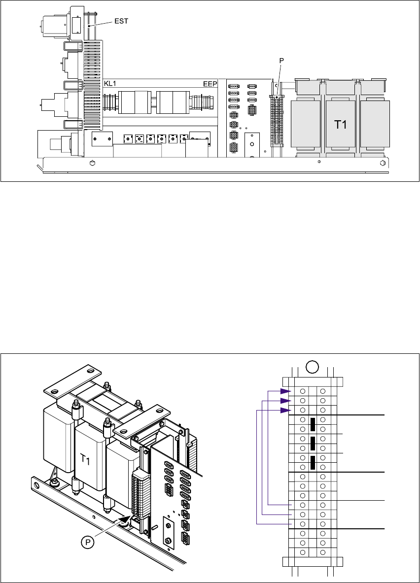
4.4.5 Overview of the parts - power supply unit - side view
Fig. 4 - 8 Overview of the parts - power supply unit - side view
EST Inrush current limiter board TG 31033-01
P Primary terminals for transformer T1
T1 Three-phase transformer
4.4.6 Converting the three-phase transformer T1 from 3 x 400 VAC to 3 x 204 VAC
Å Connect the cable from
terminal 1W3 to terminal 1W6
terminal 1V3 to terminal 1V6 and
terminal 1U3 to terminal 1U6.
Fig. 4 - 9 Primary terminals for transformer T1
PE
1U5
1W4
1V1
1U1
1W1
1U3
1V4
1U4
1V3
1W3
1V5
1W5
230VAC
230VAC
230VAC
380VAC
415VAC
415VAC
415VAC
400VAC
380VAC
380VAC
400VAC
400VAC
1V6
1U6
1W6 204VAC
204VAC
204VAC
P
Power supply S-20/S-23HM/F4/F5/F5HM/S-25HM/HS-50 Conversion Instructions
4.4 Converting the power supply from 3 x 400 VAC to 3 x 204 V ~ 03/2001 Edition
118
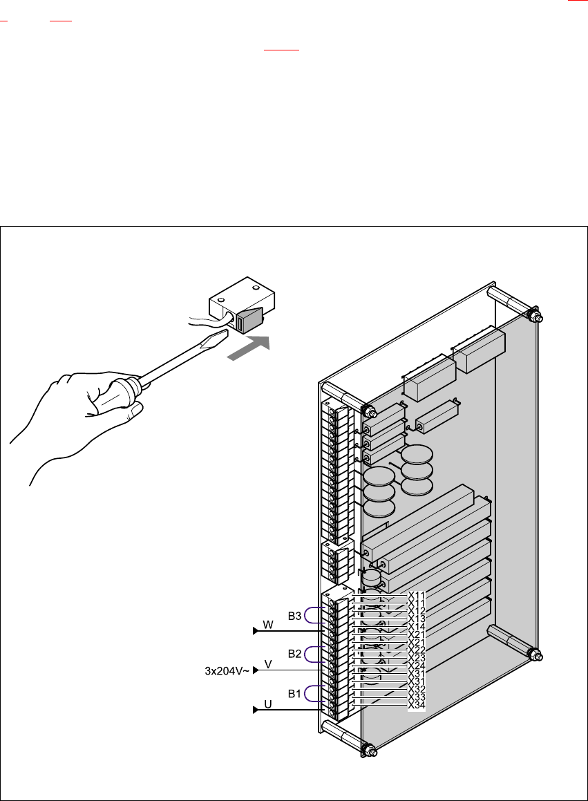
4.4.7 Reconnecting the inrush current limiter board
The inrush current limiter board is located on the back of the front panel (see item EST in Fig. 4 -
8, page 117.
Å Reconnect the following wires (see Fig. 4 - 10):
(W) from terminal X13 to terminal X14,
(V) from terminal X23 to terminal X24 and
(U) from terminal X33 to terminal X34.
Å Move the following jumpers:
B3 from terminal X12 to terminal X13
B2 from terminal X22 to terminal X23 and
B1 from terminal X32 to terminal X33.
)
Fig. 4 - 10 Reconnecting the inrush current limiter board