00192975-01.pdf - 第88页
Power supply S-20/S-23HM/F4/F5/F5H M/S-25HM/HS-50 Conversion Instruct ions 3.6 Converting the changeover table from 230 VAC t o 115 VAC 03/2001 Edition 88 3.5.7 Inserti ng plug-in adapter X1 into the service socket Å Ins…
S-20/S-23HM/F4/F5/F5HM/S-25HM/HS-50 Conversion Instructions Power supply
03/2001 Edition 3 Converting the power supply on S-20/S-23HM/ S-25HM/F4/F5 and F5HM machines
87
3.5.6 4 or 5-wire connection for the power supply
The connections are produced using either 4 or 5 wires, according to the electricity company’s
requirements. 3
4-wire connection 3
In the 4-wire connection, the neutral conductor (NE) and protective earth (PE) are combined to
form a single PEN wire. 3
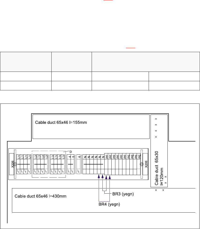
Å Insert the yellow-green wires BR3 and BR4 between the N and PE terminals in the right-hand
terminal block on terminal strip X206 (see Fig. 3 - 4
).
5-wire connection 3
In the 5-wire connection, the neutral conductor (NE) and protective earth (PE) consist of separate
wires. 3
Å Remove the yellow-green wires BR3 and BR4 from between the N and PE terminals in the
right-hand terminal block on terminal strip X206 (see Fig. 3 - 4
).
Fig. 3 - 4 Terminal block, right-hand side, terminal strip X206
Machine Terminal block
Terminal strip X206
Jumpers BR3 and BR4 between PE and N
4-wire connection 5-wire connection
S-20/F4/F5 00321510-xx Yes No
S-23HM/S-25HM/F5HM 00337342-xx Yes No
Tab. 3 - 2 Terminal blocks, right-hand side
Power supply S-20/S-23HM/F4/F5/F5HM/S-25HM/HS-50 Conversion Instructions
3.6 Converting the changeover table from 230 VAC to 115 VAC 03/2001 Edition
88
3.5.7 Inserting plug-in adapter X1 into the service socket
Å Insert the USA plug-in adapter X1 into the service socket.
3.5.8 Carry out the safety check to DIN EN 60 204
Å When the conversion is complete, carry out a safety check to DIN EN 60 204.
Å Follow the procedure described in section 2, page 72 onwards.
3.6 Converting the changeover table from 230 VAC to 115 VAC
RISK OF DEATH 3
The changeover table must be uncoupled during the rewiring work. The power cable and
communication cable must both be unplugged. 3
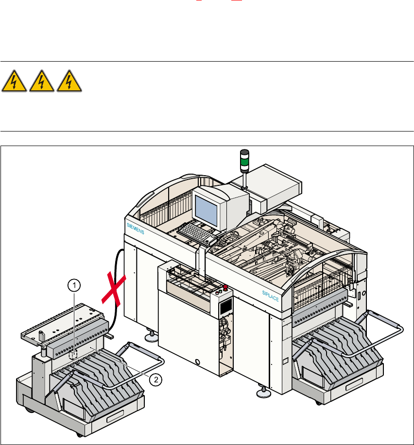
Fig. 3 - 5 Changeover table, transformer T1
a 7UDQVIRUPHU7
s 7RSSDUWRIIUDPH
S-20/S-23HM/F4/F5/F5HM/S-25HM/HS-50 Conversion Instructions Power supply
03/2001 Edition 3 Converting the power supply on S-20/S-23HM/ S-25HM/F4/F5 and F5HM machines
89
3.6.1 Converting the transformer T1 from 230 VAC to 115 VAC
Transformer T1 (item 1 in Fig. 3 - 5) can be accessed from beneath the top part of the frame
(item 2 in Fig. 3 - 5
). 3
Å Loosen the four hexagon socket-head screws.
Å Pull the cover plate over the transformer housing down and off.
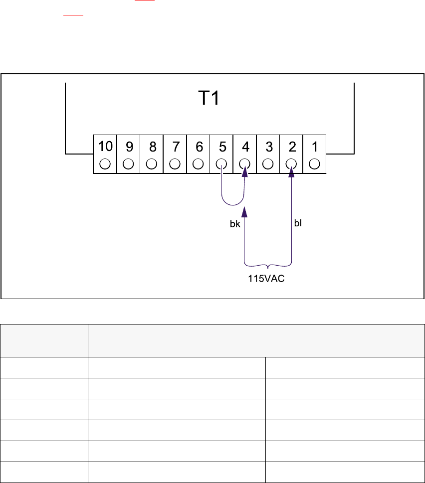
Fig. 3 - 6 Changeover table, transformer T1, terminals
Å Detach the black wire from terminal 5 and connect to terminal 4.
3.6.2 Replacing fuse F1
Å Replace the fuse in the fuse holder in the cover panel:
old rating: 3.15 A T
new rating: 6.3 A T
Voltage
Terminals
Blue wire Black wire
237 VAC 1 5
230 VAC 2 5
223 VAC 3 5
122 VAC 1 4
115 VAC 2 4
108 VAC 3 4
Tab. 3 - 3 Changeover table, supply voltages for transformer T1