00198171-02_Technical_Training_FSE_TX-Series_EN.pdf - 第109页
7 Power Supply 7.10 I / O Control Unit Distributor Technical Training FSE SIPLACE TX-Series 01/2018 109 X 8 Data Output DO8 to DO15: DO_8 Reserved (X37-12) DO_9 Buzzer (X32-5) DO_10 Indicator_1_RD Red Light tower_1 light…
7 Power Supply
7.10 I / O Control Unit Distributor
108 Technical Training FSE SIPLACE TX-Series 01/2018
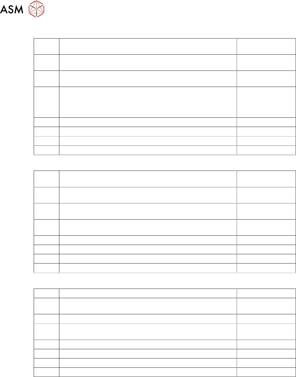
X 6 Data Input DI25 to DI31:
DI_24 Button_COTi_1 Signal from Button "COT-Insert"; Location 1.
"High": Button pressed
(X23-9)
DI_25 Hood_1 "High", when the Machine cover _1 is closed "Low",
when Machine cover _1 is open
(K1-A1+ / X26-6)
DI_25 Comp_Table_1 "High" when the COT 1 is docked, "Low" when
COT is missing
(X36-2 / X37-13)
DI_27 Hood 1_Lock_on "High" Safety switch Hood 1 activated =>
Cover cannot be opened
Low": Safety switch Hood 2 not activated => Cover can be
opened
(X26-7)
DI_28 Reserved
DI_29 S_Flap EXCo option external conveyor
DI_30 Flap lock on option external conveyor
DI_31 ID EX Co option external conveyor
X 18 Data Input DI32 to DI39:
DI_32 Fan_G1 Loc.1 Input for Fan Control: "Low": Fan Revolution is ok;
"High": Fan Revolution is below the threshold value
(X34-1)
DI_33 Fan_G2 Cover-1 Input for Fan Control: "Low": is ok; "High": Fan
Revolution is below the threshold value
(X34-2)
DI_34 Fan_G3 Loc.2 Input for Fan Control: "Low": Fan Revolution is ok;
"High": Fan Revolution is below the threshold value
(X34-3)
DI_35 Fan_G4 Loc.2 Input for Fan Control: "Low": Fan Revolution is ok;
"High": Fan Revolution is below the threshold value
(X34-4)
DI_36 Reserved
DI_37 Fan Power Supply
DI_38 Reserved
DI_39 Reserved
X 7 Data Output DO0 to DO7:
DO_0 Reserved (X37-11)
DO_1 SW_Ctrl_On ("Software release") The machine can only start
when this signal is "High"-Signal (24V OK)
(X23-2 / X24-2
DO_2 Reserved (X31-8)
DO_3 Pressure_PV1 Signal an proportional valve_1. "High": Valve
switches air pressure on; "Low" Valve is not switched
(X31-7 (via R15K))
DO_3 Hood_Lock2 "High" Safety switch locking device an Cover 2 (X27-2)
DO_5 Hood_Lock1 "High" Safety switch locking device an Cover 1 (X26-2)
DO_6 Reserved
DO_7 Interior_light "High"-Interior light ”on” "Low"-Interior light ”off” (X30-7)
7 Power Supply
7.10 I / O Control Unit Distributor
Technical Training FSE SIPLACE TX-Series 01/2018 109
X 8 Data Output DO8 to DO15:
DO_8 Reserved (X37-12)
DO_9 Buzzer (X32-5)
DO_10 Indicator_1_RD Red Light tower_1 lights with “High“ at Port Out-
put
(X32-4)
DO_11 Indicator_2_RD Red Light tower_2 lights with “High“ at Port Out-
put
(X32-9)
DO_12 Indicator_1_GNThe green Light tower_1 lights with “High“ at Port
Output
(X32-1)
DO_13 Indicator_2_GNThe green Light tower_2 lights with “High“ at Port
Output
(X32-2)
DO_14 Indicator_1_YEThe yellow Light tower_1 lights with “High“ at Port
Output
(X32-7)
DO_15 Indicator_2_YEThe yellow Light tower_2 lights with “High“ at Port
Output
(X32-6)
X 17 Data Output DO16 to DO23:
DO_16 Service for integration tests (X25-9)
DO_17 Service for integration tests (X25-11)
DO_18 Service for integration tests (X25-12)
DO_19 Reserved
DO_20 Reserved
DO_22 Reserved
DO_23 Reserved
DO_24 Reserved
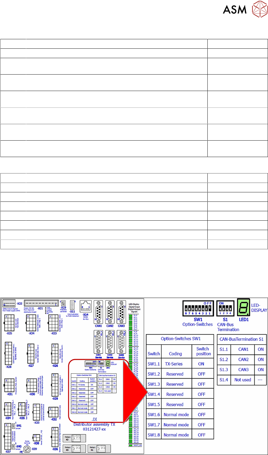
Data exchange with the power supply unit SMPS
The interface allows data exchange with the power modules of the SMPS (Switched Mode Power
Supply). For example voltages dips from the customer main net can be seen at the station soft-
ware.
I/O Distributor Assembly DIP Switches
7 Power Supply
7.11 Analysis - Common Error List
110 Technical Training FSE SIPLACE TX-Series 01/2018
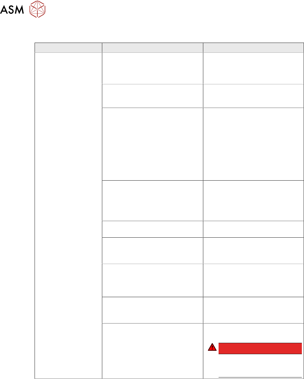
7.11 Analysis - Common Error List
Error Possible Cause Action
No reaction after
START pressed
Duration of pressing and release of
START button
●
Press longer than 200 ms and
shorter than 1500 ms.
START should be accepted on
pushbutton release.
Safety loop closed?
●
Check if both channels of
safety loop show closed con-
dition
SW_CTRL_ON output of IO miss-
ing?
●
Check: (X29.A6) should be
HIGH if START is pressed
●
Check IO wiring.
●
Check IO output.
●
Check START button wiring.
If output is missing:
●
Replace IO unit
●
Fix START button wiring.
Connection to PCB FD.A1 estab-
lished?
●
Check connectors X24A and
X24B at FD.A1 and at PCB
CSB
●
Place connectors firm in posi-
tion.
Ground connection of PCB CSB
missing?
●
Connect terminal lug to
Ground terminal of CSB.
Supply voltage of CSB missing?
●
Check fuses F12 and F13.
●
Replace fuses F12 and F13, if
needed.
Signal PCC-POWER-OK (X24B.5
at PCB,LED at K5)
If voltage reading > 22V or Power
OK LED of K5 is on→ internal de-
fect of CSB:
●
Replace unit
24V Measure input voltage
(X24B.3)
If voltage reading > 22V → internal
defect of CSB:
●
Replace unit
Power connectors of CAP and CSB Connectors should be firm in posi-
tion.
DANGER!
If you check connectors
mind the dangerous
voltage!
.