00198171-02_Technical_Training_FSE_TX-Series_EN.pdf - 第129页
8 Control and Communication 8.10 VISION GigE Technical Training FSE SIPLACE TX-Series 01/2018 129 Vision GigE Overview Power Vision GigE Overview Camera Communication
8 Control and Communication
8.10 VISION GigE
128 Technical Training FSE SIPLACE TX-Series 01/2018
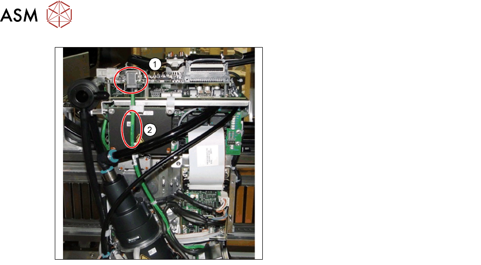
1. Ethernet connectors
2. Communication via Ethernet cable (may
be black or green)
●
GigE is an interface standard for high-performance industrial cameras. It provides a frame-
work for transmitting high-speed video and related control data over Ethernet networks.
●
It’s incompatible to the existing SIPLACE Vision System Hardware.
●
A GigE-network interface card (Ethernet Adapter) is inside the BoxPC.
●
All GigE cameras use the same sensor type number as for SIPLACE Vision with an additional
G at the end, e.g. SST23G.
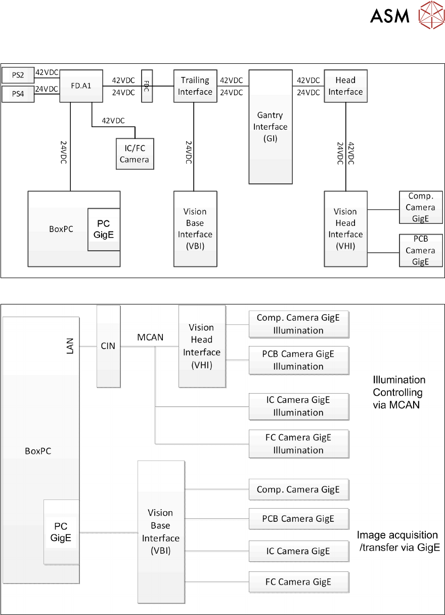
The Vision communication on TX over GigE and CAN bus
●
The images from the Component and PCB cameras are sent digitally to the Vision Base Inter-
face (VBI).
●
The transfer takes place via the trailing cable “Spread Spectrum“ (without coax cable).
●
The images from the IC and FC cameras are sent directly to the GigE adapter in PC via the
Vision base Interface (VBI).
●
The machine CAN bus provides the illumination control.
●
The individual illumination values stored in the component shape are transferred to the cam-
era via CAN bus.
8 Control and Communication
8.10 VISION GigE
Technical Training FSE SIPLACE TX-Series 01/2018 129
Vision GigE Overview Power
Vision GigE Overview Camera Communication

8 Control and Communication
8.11 Analysis - Common Error List
130 Technical Training FSE SIPLACE TX-Series 01/2018
8.11 Analysis - Common Error List
Code Error Description Possible Cause Action
30447
30451
30456
30256
30262
●
Communication on GCU-
GCU fast drive bus inter-
rupted
●
Specified CAN bus is
switched off
●
Secondary CAN bus is off
●
Cannot initialize CAN
hardware
●
Cannot initialize CAN inter-
face
●
Problem with cable
connection
●
Problem with CIN
●
Problem with certain
content/board in the
CAN circuit
●
Defective MGCU
●
Defect adapter/HCU
●
Check cable con-
nection
●
Restart the
machine
●
Check the status
and switch setting
on the CIN
●
Check and redown-
load firmware of
the CAN interface
●
Check status / in-
dication on the
board related in
CAN circuit
●
Check status / in-
dication of MGCU/
HMCU
●
Replace adapter/
HCU
37752
●
The LED test of the cam-
era illumination failed
●
No image captured from
camera
●
Power for illumination
of camera failed
●
LED failed but camera
can be operated
●
Problem with camera
GigE
●
Problem of cable GigE
●
Check relevant cir-
cuit of power for il-
lumination
●
Check output relev-
ant power supply
(PS)
●
Check the function-
ality of camera
●
Check connection
of the GigE cable
33378
33520
33606
33331
●
Camera cannot be ad-
dressed
●
Board camera cannot be
addressed
●
Image capture from cam-
era canceled
●
Signal path between
PC and camera inter-
rupted
●
Problem with camera
●
Check cable con-
nection on BoxPc
●
Check the coax
cable connection
and trailing cable
connector
●
Check the camera
cable
●
Check the camera
and replace if ne-
cessary
30365
30572
●
Moving the axis is not per-
mitted, Z Axis is not in a
safe position
●
Incorrect time sequence
when moving Star and Z
Axis
●
Sporadic communica-
tion error for axis con-
trol sequence
●
Permitted overlap re-
gion of Star and Z
been reached
●
Perform head axis
reference run
●
Check the head
and axis
●
Perform overall ref-
erence run
●
If certain segment
defective, replace it