00198171-02_Technical_Training_FSE_TX-Series_EN.pdf - 第114页
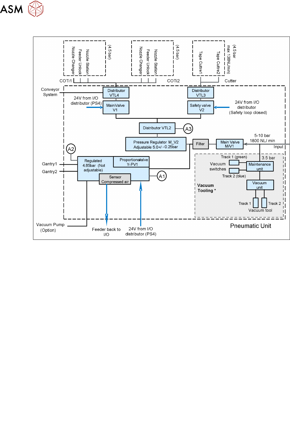
7 Power Supply 7.14 Excercise: Power Supply 114 Technical Training FSE SIPLACE TX-Series 01/2018 Overview Pneumatic Diagram * Only for TX machines with installed vacuum tooling. For detailed information about setting up …
7 Power Supply
7.13 Pneumatic System Overview
Technical Training FSE SIPLACE TX-Series 01/2018 113
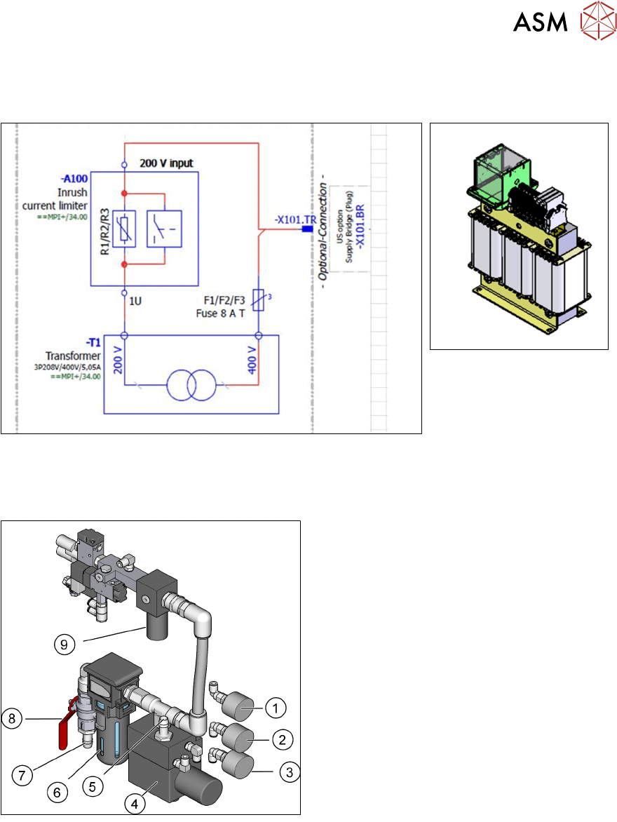
In case of mains voltages below 360 VAC (3*200 - 230 V AC) voltage adaption to input voltages
380 - 480 VAC has to be provided. This is done by an US voltage adaption kit.
The transformer is found in the machine base close to the Box PC.
7.13 Pneumatic System Overview
Pneumatic System – Parts Overview
1. Pressure gauge for supply pressure of the
machine components (5 ± 0,25 bar)
2. Pressure gauge for supply pressure of the
Gantry 1/2 (4,85 ± 0,1 bar)
3. Pressure gauge for input air (5.0 – 10.0
bar)
4. Proportional valve
5. Compressed air supply for gantries
6. Compressed air filter
7. Compressed air input
8. Stop Valve
9. Pressure regulator
7 Power Supply
7.14 Excercise: Power Supply
114 Technical Training FSE SIPLACE TX-Series 01/2018
Overview Pneumatic Diagram
* Only for TX machines with installed vacuum tooling.
For detailed information about setting up the vacuum tooling refer to the installation manual "Basic-
Pack Vacuumtooling", order number 03149358-01.
7.14 Excercise: Power Supply
1. Which of the following statements is incorrect?
A The TX uses a Switch Mode Power Supply (SMPS).
B Standard power input is 3 x 360 V~415 V ± 10%; 50/60 Hz.
C The voltages from PS1-PS4 modules need be adjusted after exchange of a PS module.
D The CAP1 is used instead of ballast card and resistor.
2. Before commencing work on the SMPS, what’s pre-condition must be met.
A Switch off the machine and wait for 5 mins.
B Switch off machine, and wait until the PS1 LED status is off.
C Switch off machine and disconnect the cable from PS1.
D Switch off machine, wait for 5 mins, and then measure the voltage between X303 and X305,
X304 and X305, the voltage should be lower than 5V.
3. Which of the following is correct if the output cable from PS1 is disconnected?
A Machine is stopped. Diagnostic GUI display the following error "PS1 has no power".
B Machine is stopped. Diagnostic GUI displays the following warning: PS1 is no power.

7 Power Supply
7.14 Excercise: Power Supply
Technical Training FSE SIPLACE TX-Series 01/2018 115
C Machine is stopped. No any error or warning issued from diagnostic system, and the icon for
PS1 will no longer be displayed in the diagnostic GUI.
D Machine is stopped. Diagnostic system is counter displays a one-time power drop.
4. Power of MGCU: 27VDC come from PS3; 300VDC come from PS1.
True …………………………………………………………………………………………………
False …………………………………………………………………………………………………
5. Explain diagnostic systems for the SMPS, draw a simple circuit diagram if possible.
………………………………………………………………………………………………………
………………………………………………………………………………………………………
………………………………………………………………………………………………………
………………………………………………………………………………………………………