00198171-02_Technical_Training_FSE_TX-Series_EN.pdf - 第126页
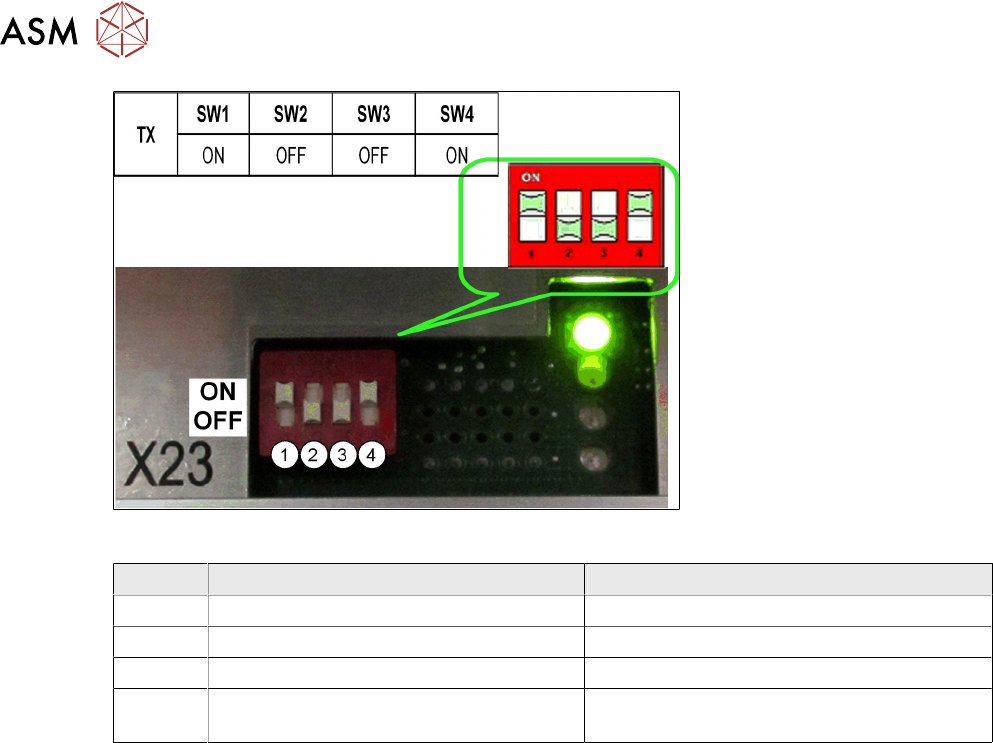
8 Control and Communication 8.8 FCU 126 Technical Training FSE SIPLACE TX-Series 01/2018 Switch settings ON OFF SW1 Test mode for reject bins deactivated Test mode for reject bins activated SW2 60 Fold FCU 40 Fold FCU SW…
8 Control and Communication
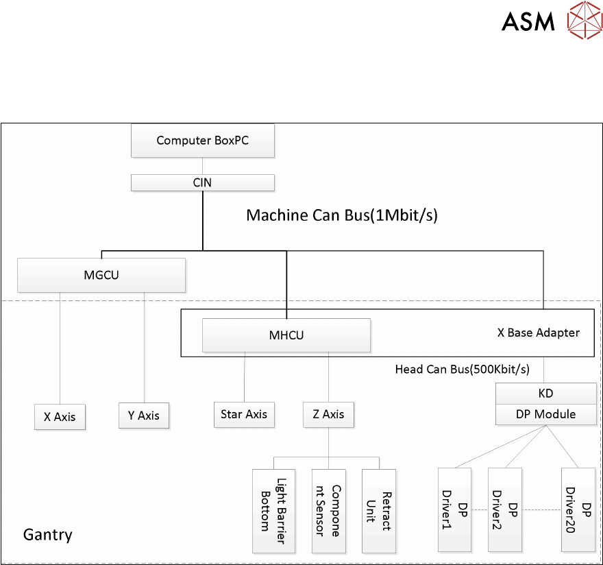
8.7 Axis Control
Technical Training FSE SIPLACE TX-Series 01/2018 125
8.7 Axis Control
Axis Control
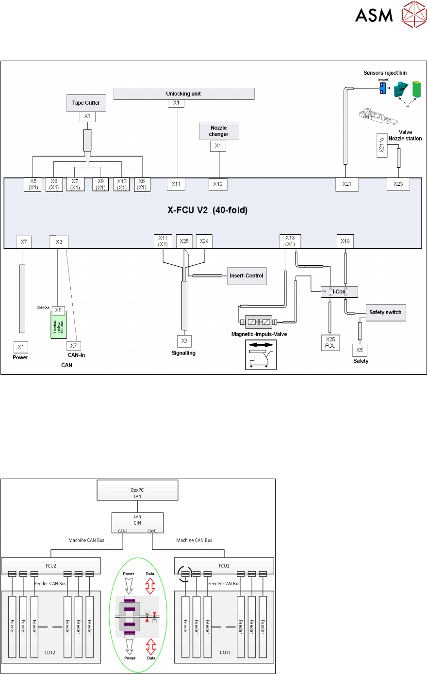
8.8 FCU
The FCUs (Feeder Control Unit) on TX machines has the basically functionality:
●
Communication with the feeders and docking of the COT.
●
Control of the tape cutter (moving the pneumatic cylinders in and out, status query of the
sensors).
●
Nozzle changers detection and the nozzle station (forced air valve for the C&P20 and CPP)
control.
●
Query of the sensors for the component/nozzle reject boxes.
During production with (SW1= OFF) the reject bin is recognized by the sensor and signalized by
the LED.
The FCU need to be addressed for the TX see diagram below:
8 Control and Communication
8.8 FCU
126 Technical Training FSE SIPLACE TX-Series 01/2018
Switch settings
ON OFF
SW1 Test mode for reject bins deactivated Test mode for reject bins activated
SW2 60 Fold FCU 40 Fold FCU
SW3 Without insert control with virtual button With insert control without virtual button
SW4 HW version 8 with tape cutter and nozzle
changer functions
HW version without tape cutter and nozzle
changer functions
8 Control and Communication
8.9 Feeder Communication
Technical Training FSE SIPLACE TX-Series 01/2018 127
Control and Communication – FCU Overview
8.9 Feeder Communication
The communication between the Feeder Control Unit (FCU) and the X-feeders is carried out via an
internal CAN bus.
This CAN bus is only responsible for the communication between the FCU and the feeders and is
controlled by the machine CAN bus.
The data and power supply from the FCU to each feeder is contactless.
8.10 VISION GigE
GigE is the term used for the vision system hardware including camera types and a bus structure
on TX machine.