00198171-02_Technical_Training_FSE_TX-Series_EN.pdf - 第112页
7 Power Supply 7.12 US option 112 Technical Training FSE SIPLACE TX-Series 01/2018 Error Possible Cause Action DC24-S is missing Fuse does not work? Connector X24A (both PCB ’ s!) properly connected? ● Check supply volta…

7 Power Supply
7.11 Analysis - Common Error List
Technical Training FSE SIPLACE TX-Series 01/2018 111
Error Possible Cause Action
Short reaction of CSB
after START pressed
●
Check precharge current at
300 V DC link voltage
If there is no precharge current
(max 10A):
●
Check GND connection of
CSB
Ground connection of PCB CSB
missing?
●
Connect terminal lug to
Ground terminal of CSB.
If there is GND connection estab-
lished:
→ internal defect of CSB;
●
Replace unit
Overload or short circuit at 160 V
DC link output?
●
Remove X24B and try to start.
If Start is working now fix short cir-
cuit conditions at 160V DC link
branch
Overload or short circuit at 300 V
DC link voltage?
●
Remove X21 and X22 and try
to start.
If Start is working now fix short cir-
cuit conditions at 300V DC link
branch
Machine is passing ref-
erence run but stops at
beginning the of pro-
duction run
MGCU Error Message: Under-
voltage error at DC link voltage?
●
Check capacitor value of CAP
unit (service screen of dia-
gnostic functions) has to be >
30 mF
If Capacitor value < 30 mF:
●
Replace capacitor unit
●
Check QT40.999 error mes-
sages at service screen
If QT40 error is shown:
●
Replace QT40 unit.
Service screen QT40 unit
●
Check indicator lights at
QT40-999:
Green light (>220V) should be on
during reference run
red light should be on temporary
during gantry acceleration period
DC 42V-S is missing
(Conveyor supply)
Fuse does not work?
Connector X24A (both PCB’s!)
properly connected?
●
Check supply voltage at
FD.A1, F16
Fuse blown or broken?
●
Replace fuse
●
Place connector firm into
place
If error still occurs
→ internal defect of CS:
●
Replace unit

7 Power Supply
7.12 US option
112 Technical Training FSE SIPLACE TX-Series 01/2018
Error Possible Cause Action
DC24-S is missing Fuse does not work?
Connector X24A (both PCB’s!)
properly connected?
●
Check supply voltage at
FD.A1, F11
Fuse blown or broken?
●
Replace fuse
●
Place connector firm into
place
If error still occurs
→ internal defect of CSB:
●
Replace unit
POWER-Enabled sig-
nal is missing
Fuse does not work?
Connector X24A (both PCB’s!)
properly connected?
Precharge sequence finished?
DC link voltages are ON)?
●
Check supply voltage at
FD.A1, F11
Fuse blown or broken?
●
Replace fuse
●
Place connector firm into
place
If error still occurs
→ internal defect of CSB:
●
Replace unit
Errors at diagnostic interface:
Error Possible Cause Action
No diagnostic display
(Icon is missing)
Wiring of diagnostic master:
●
Connection between PS1 and
CAP established?
●
Connection between CAP and
IOCU2 established (use cros-
sover cable!)?
●
Replace wiring.
If there is still no Diagnostic display
available → Diagnostic master at
CAP unit failure:
●
Replace CAP unit
●
QT40 diagnostic supply
voltage available?
●
Internal fuse at CAP unit
blown?
Voltage reading between Pin 1 and
4 of diagnostic connector should be
DC 5V
●
Check QT40 diagnostic supply
voltage.
●
Check internal fuse at CAP
unit.
●
Check voltage reading
between Pins 1 and 4 of dia-
gnostic connector.
If there is no voltage reading →
CAP unit failure:
●
Replace CAP unit
No fuse diagnostic dis-
play
Wiring to FD.A1:
Connection between FD.A1 and
IOCU2 establisched?
●
Check if FD.A1-X3 is located
firm in its place.
If not:
●
Replace wiring
If there is still no Fuse diagnostics
available:
→ FD.A1 internal error.
●
Replace FD.A1
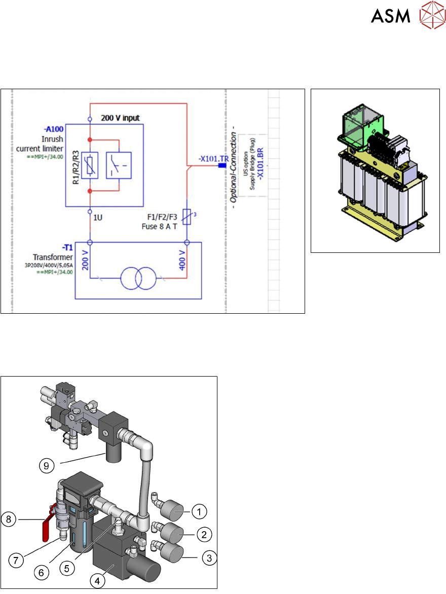
7.12 US option
All the power packs used in the SMPS of series QT40 have a permissible input voltage of 380V –
480V.
7 Power Supply
7.13 Pneumatic System Overview
Technical Training FSE SIPLACE TX-Series 01/2018 113
In case of mains voltages below 360 VAC (3*200 - 230 V AC) voltage adaption to input voltages
380 - 480 VAC has to be provided. This is done by an US voltage adaption kit.
The transformer is found in the machine base close to the Box PC.
7.13 Pneumatic System Overview
Pneumatic System – Parts Overview
1. Pressure gauge for supply pressure of the
machine components (5 ± 0,25 bar)
2. Pressure gauge for supply pressure of the
Gantry 1/2 (4,85 ± 0,1 bar)
3. Pressure gauge for input air (5.0 – 10.0
bar)
4. Proportional valve
5. Compressed air supply for gantries
6. Compressed air filter
7. Compressed air input
8. Stop Valve
9. Pressure regulator