00198171-02_Technical_Training_FSE_TX-Series_EN.pdf - 第27页
3 Setting Up the Machine 3.1 Setting up the TX Machine Technical Training FSE SIPLACE TX-Series 01/2018 27 3 Setting Up the Machine 3.1 Setting up the TX Machine Checking a delivery ● Store the machine in the packaging c…

2 Machine Basic Overview
2.8 Featchers to Achieve high Accuracy with the TX micron
26 Technical Training FSE SIPLACE TX-Series 01/2018
●
Higher resolution of linear scales for main axes
●
Reference glass bars (with very low coefficient of thermal expansion (CTE))
●
Double resolution of star axis encoder in CP20M2 head compared to CP20 P head
●
Added calibration and recalibration routines
Accuracy of 15µm @ 3σ
●
Enhanced & stiffer conveyor system
●
Vacuum tooling made of material with low coefficient of thermal expansion and additional
●
Reference glass bars at the vacuum tooling
Accuracy of 20 µm @ 3σ
To achieve an even higher accuracy than the 25 µm @ 3σ with the CP20M2 head the high preci-
sion flag (HPF) is available at SIPLACE TX micron.
The HPF can be activated in SIPLACE PRO per component shape.
Note: Today there is no possibility to set the high precision flag per placement position.
Every component for which the HPF is activated will be placed with an accuracy of 20 µm @ 3σ us-
ing the HPF will have impact the placement speed.
The speed reduction depends on the amount of components with HPF and available heads in line.
Accuracy of 15 µm @ 3σ for TX 2i micron 15
To achieve the accuracy of 15 µm @ 3σ following preconditions are required:
●
SIPLACE TX2i micron 15
●
Special vacuum tooling with high accuracy glass bars in the front and rear of the substrate
●
High precision flag set for 15µm for the components shapes required
Note: A SIPLACE TX2i micron cannot be upgraded to a SIPLACE TX2i micron15.
Customer specific vacuum tooling’s for TX 2i micron 15
In order to run the TX micron 15 a customer specific vacuum tooling is required.
Therefore 3 different vacuum tooling bases for different PCB size are available.
The top plate of the vacuum tooling can be exchanged and is product specific.
Therefore when ordering a vacuum tooling for the TX micron a product specific – tooling plate
needs to be designed and manufactured. Therefore the exact dimension (X,Y,Z) of the PCB is re-
quired. Best is to have the drawing and if possible a sample board in order to design the board.
The according items are:
●
Vacuumtooling SIPLACE TX 100mm width
●
Vacuumtooling SIPLACE TX micron 55 mm <= 67 mm.
●
Vacuumtooling SIPLACE TX micron 68 to 100mm
3 Setting Up the Machine
3.1 Setting up the TX Machine
Technical Training FSE SIPLACE TX-Series 01/2018 27
3 Setting Up the Machine
3.1 Setting up the TX Machine
Checking a delivery
●
Store the machine in the packaging crate until room temperature has been reached. There is
otherwise a risk of condensation occurring.
●
Check the delivery for damage.
●
Check the shock sensors.
●
Unpack the machine and the accessories and check the delivery for completeness (reference
delivery note).
●
Document the result in the installation report / acceptance testing report.
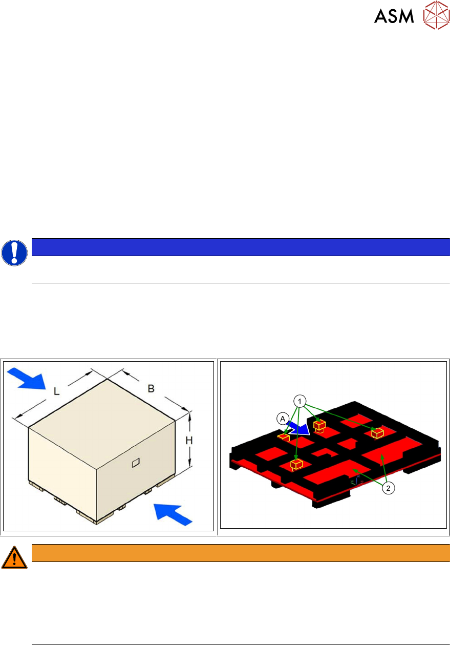
NOTICE
Always use a pallet and a forklift truck to transport the machine over longer distances in or-
der to avoid damaging the machine.
Attachment points on the transport crate or pallet
Attach the forklift truck only at the points identified by (A).
1. Machine feet: The machine feet are fixed with 3 angle brackets on the pallet
2. Component table position on the pallet
WARNING
Make sure that the forks are evenly loaded when you lift the machine.
► A firm support between the forks and machine will prevent the machine tilting when it
is raised. This will also prevent a one-sided load on the machine feet, which would de-
form the fixing of the machine feet.
► It is recommended that a second person watch the machine as it is raised to make
sure that the machine does not tip to one side when lifted by the forklift truck.
3 Setting Up the Machine
3.1 Setting up the TX Machine
28 Technical Training FSE SIPLACE TX-Series 01/2018
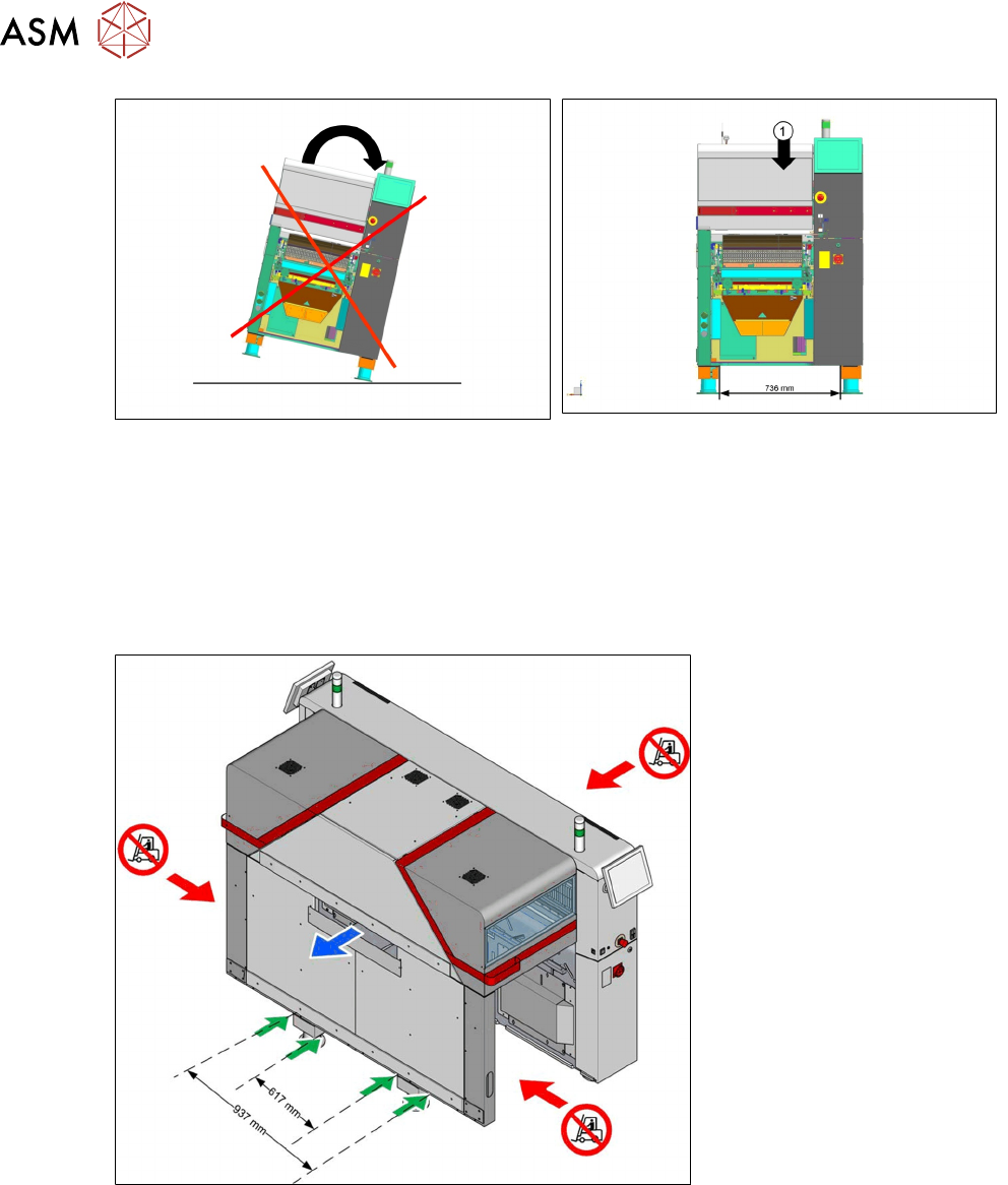
1. The balance point of the machine is not the center of the machine.
●
Attention: Don`t use the Input Side of the machine to lift up.
●
Please use the Output Side with a minimum fork of 617mm or with a distance between the
forks of 937mm.
●
Don`t move the machine outside of the center from the machine.
●
Move with fork next to the feet only; there is no other way to move the machine in line.
Leveling the machine
Please align the machine with 3 feet (1) and then fix the 4th foot (2) so that there is contact to the
ground.
It is easier to use the 2 feet at location 2 for leveling and fix last the 4th foot at location 1.