00198171-02_Technical_Training_FSE_TX-Series_EN.pdf - 第51页
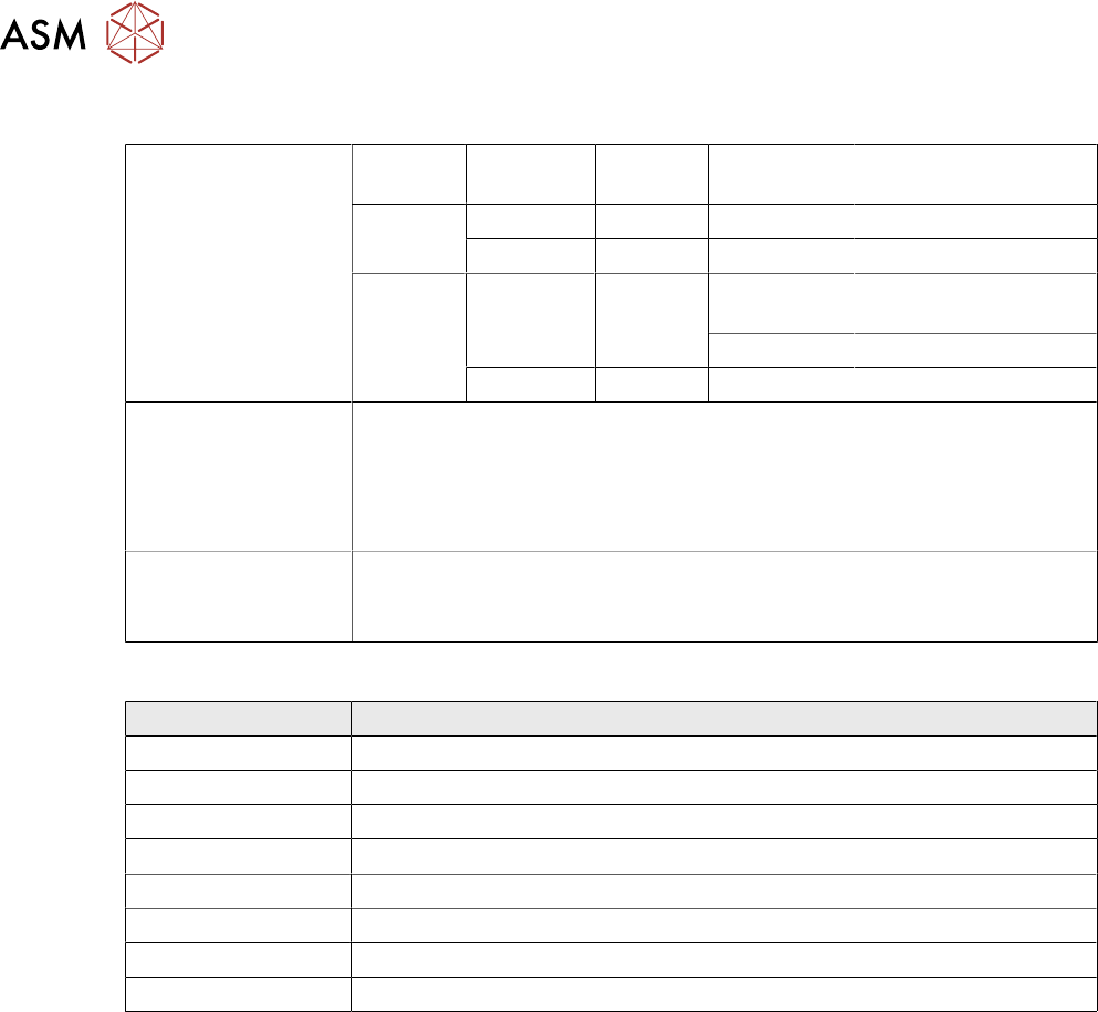
5 Component Supply 5.2 Docking Station and COT Insert Technical Training FSE SIPLACE TX-Series 01/2018 51 1. Drilling Hole 2. Cotter Pin 3. Table plate CAUTION The COT height should match the machine transport height as …
5 Component Supply
5.1 Change Over Table (COT)
50 Technical Training FSE SIPLACE TX-Series 01/2018
5.1.3 COT Feeder Configuration
Feeder capacity
(Track width 8mm)
Machine Locations With
C&P20 P
With CPP With Twin Head
(only Location1)
TX2i Location 1 38 tracks 40 tracks Not Applicable
Location 2 38 tracks 40 tracks Not Applicable
TX1
TX2
Location 1 38 tracks 28 tracks
with JTF
28 tracks with JTF
40 tracks 40 tracks
Location 2 38 tracks 40 tracks 40 tracks
COT/Feeder inter-
faces to the
machine:
Automatic connection to machine during docking (no cables needed)
Feeder power supply
Feeder communication
Machine safety loop
Feeder compressed air connection
COT heights: 900 mm ± 15 mm
930 mm ± 15 mm (standard height)
950 mm ± 15 mm (SMEMA height)
The following SIPLACE Feeders can be used on the TX machine:
Name Type
X-Feeder Tape feeder types 4 mm X – 56 mm X
Linear feeders Linear feeder types _3x95Ax and _2x15Ax and_ 30Ax
Stick feeders Type smart stick_3x95X and _ 2x15X and _30X
Label feeder Tape feeder type label presenter Ax
LDU-X Processing feeder type Linear Dipping Unit X
GlueFeeder Processing feeder type GlueFeeder X
SIPLACE JTF-ML Tray feeder type JTF-ML_18X and JTF-ML_14X
Reject plate Reject plate TX
Restrictions LDU-X
●
There is a restricted pick-up area when using the LDU-X.
The LDU-X might not be place on the outer 6 tracks (left and right).
This results in restrictions in terms of component processing area.
●
The LDU-X can run together with CP20 P/M2, CPP and TH (only TX series). The LDU-X must
be manually placed in the set up.
●
Dipping area in Y-direction and access restriction on LDU for inner segment nozzle TH (only
TX-Series).
5.1.4 Height Adjustment
The COT height can be adjusted so that the transport heights of 900, 930 and 950 mm can be
reached.
The different default heights can be adjusted using the two cotter pins from the hollow shaft, placed
in three different positions.
●
A second person is needed for lifting the plate of changeover tables.
●
Raise the changeover table plate (3) slightly and knock the pins (2) out of the left and right
hollow shafts.
●
Move the table plate to the correct height.
●
Put back the 2 cotter pins (2) into the drilling hole (1) of the sleeve shaft.
●
Now the height had been adjusted.
5 Component Supply
5.2 Docking Station and COT Insert
Technical Training FSE SIPLACE TX-Series 01/2018 51
1. Drilling Hole
2. Cotter Pin
3. Table plate
CAUTION
The COT height should match the machine transport height as incorrect settings can lead
to damage when inserting or removing COT.
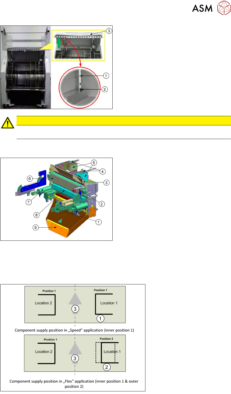
5.2 Docking Station and COT Insert
1. Docking claws (on the machine frame)
2. Safety switch
3. Empty tape duct
4. Nozzle station
5. Reject bin
6. FCU
7. Cylinder for claw
8. Feeder unlock device
9. Waste tape chute
●
The COT position is configured as "Speed application" for TX2i or "Flex application" for TX1
and TX2.
●
"Speed application" both location COT at inner position.
●
"Flex application" location 2 at inner position and location 1 at outer position.
●
Only location 1 is possible for the outer position.
1. Inner position
2. Outer position
3. Transport direction
5 Component Supply
5.3 Feeder Control Unit (FCU)
52 Technical Training FSE SIPLACE TX-Series 01/2018
Docking
●
The docking process can only be performed when the machine is on, compressed air is sup-
plied to the machine and the safety covers are closed.
●
To dock the changeover table, push the table as far as possible up to the feed device and
press the button on the machine.
●
On the left and right from the empty tape duct are two centering pins to center the COT for the
final correct pick up position.
●
The feeder contact plate is raised by two pneumatic cylinders and cam disks while, at the
same time, the entire changeover table is pulled into the machine.
Undocking
●
To undock, make sure the compressed air is switched on and control system off and then
press the button on the machine frame.
●
The changeover table is released by the feed device and is pushed out and lowered by two
additional pneumatic cylinders fixed to the left and right of the empty tape duct.
●
The COT will be automatically disconnected from the machine.
●
When the machine is switched off or there is no compressed air supply, the changeover table
can be easily pulled out of the machine by taking hold of the handles.
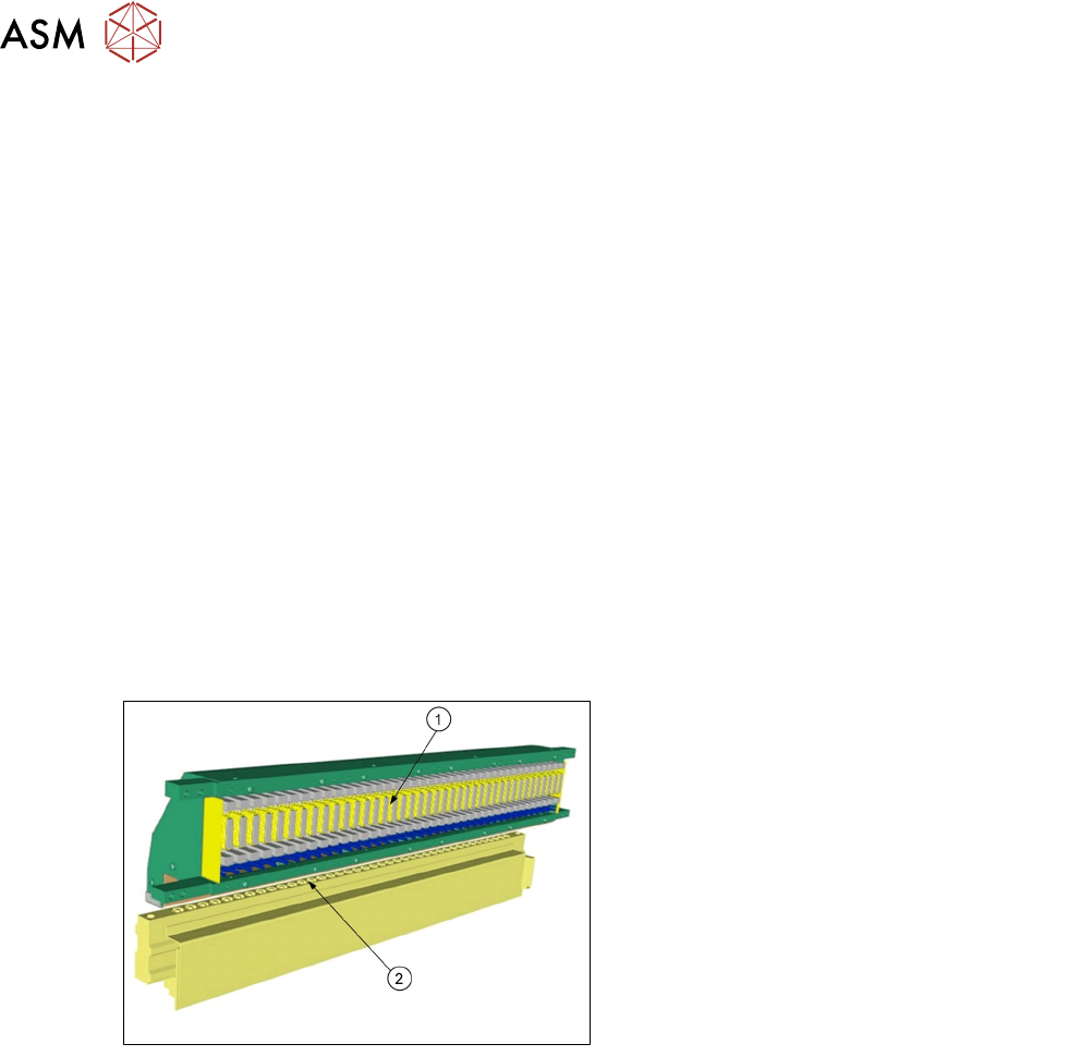
5.3 Feeder Control Unit (FCU)
1. FCU (Feeder Control Unit)
2. Feeder unlock device
●
The FCU is supplied with 28V from the
PULS power supply, all the other internal
voltages (e.g. 24V) are produced intern-
ally.
●
All important voltages are monitored by the
processor. In case of a violation of pre-
defined limits the complete module is shut
down!
The FCU has the following functionality:
●
Triggering of X-feeders and the triggering of the feeder unlock device.
●
Docking unit control.
●
Safety loop and safety message.
●
Triggering of the tape cutter.
●
Triggering of nozzle changers and triggering of the nozzle station (blowing clear)
●
Monitoring of the sensors for the reject bins.