AOI_RS_v85_en.pdf - 第101页
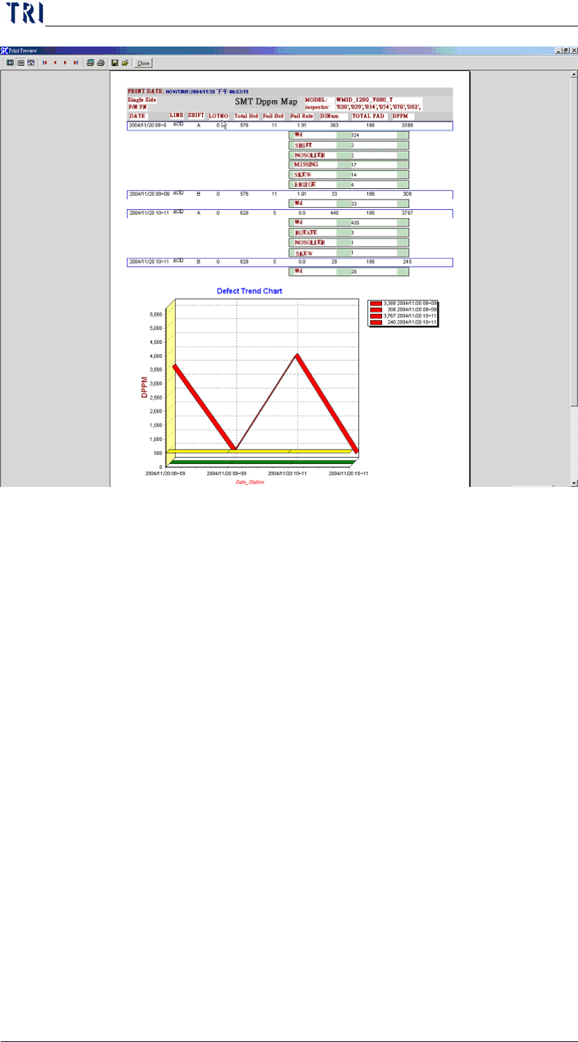
Chap ter3 SPC User Ma nual AOI Repair Station 97 Step3. C lick on [PRINT] [SINGLE SIDE], [P/N] may be entered manuall y before pressing [PRINT] on the previous screen The limitation of the [DEFECT TREND CHAR T] may b…

Chapter3 SPC User Manual
AOI Repair Station
96
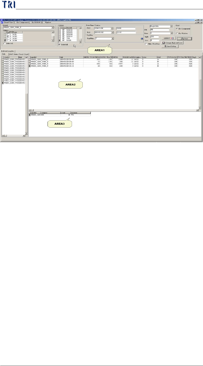
6 DATE SORT
Sorts by date and time(two hours per unit)calculates defect components in
detail
Step1. Select [MODEL], [STATION], [DATE TIME], [Repair staff
(USER)], [TOP/BTM (* no separation of top or bottom)] and
[LOT_NO (deselect for all)]. The false alarm characters will be
filtered when the [FILTER WORDPASS] is check marked.
Step2. Click on [QUERY]. The MODEL is sorted by date 2004/11/20
08~09 and its basic information in AREA2, and details of DEFECT
information on this MODEL in AREA3
Chapter3 SPC User Manual
AOI Repair Station
97
Step3. Click on [PRINT]
[SINGLE SIDE], [P/N] may be entered manually before
pressing [PRINT] on the previous screen
The limitation of the [DEFECT TREND CHART] may be
entered manually on the previous screen, press [change high
and low] after the key in, and then press [PRINT] to change
the limitation automatically.
Definitions
DATE-Date and Time
LINE-Station
SHIFT-Work shifts
LOTNO-Lot number
TOTAL BOARD-Total number of boards
FAIL BOARD-Defect boards
FAIL RATE-Failboard / totalTestBoard * 100
DPPM-DJNUM/(number of single face joint points *number of test
boards) * 1000000
DJNUM-number of bad joint point
TOTAL PAD-Total COMPONENT on this board
Chapter3 SPC User Manual
AOI Repair Station
98
7 X Bar R Chart
7.1 Setting
Select [Utility/ Inline Component Data Output to SPC] in AOI main
program.
Set [Setting/Defect Warning/ Output7100XY] as [True] in Ptril.exe
program on Repair Station PC.
7.2 Objective
This function shows the stability and capability of the process for
reference by the operator in deciding whether or not to adjust the
process or machine. In addition, it includes error management
parameter setting so that once the data in the control chart hits the error
parameters, the system automatically sends out an alarm. Currently,
this software is applicable to these two types of test machines: TR7006
and TR7100. This document will explain how to use this software
package. The following figure shows the main menu of this function.
7.3 Explanation - Main Frame
The main menu can be divided into the Function menu area, Real-time
monitor setup area, Real-time monitor spec. data area and Real-time