YesAX V3.1.2 - Software User Manual.pdf - 第127页
General Inspecti on Methodolo gy 10 - 33 The To Lead Align button changes the focus from the Solder Alignment dialog box to the Lead Alignment box. The Help button launches internal help for this dialog. 10.5 X-Ray Inspe…
10-32 General Inspection Methodology
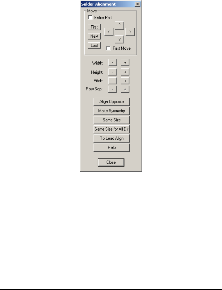
10.4.7 Solder Alignment
Using this dialog the user can move and size the solder inspection boxes.
Select Align.. from the Solder pop-up menu to open the Solder Alignment dialog.
The Width and Height buttons increase and decrease the rectangular area of the inspection box.
The Pitch buttons increase or decrease the pitch between inspection boxes.
The Row Sep. buttons are normally disabled. They are enabled only if the Row Count is greater
than 1. When they are enabled it adjusts the row separation for the pins.
The Align Opposite button aligns or creates the lead inspection in the opposite direction of the
part.
The Make Symmetry button moves the lead box so that it is symmetrical with respect to the
centroid of the part.
The Same Size button makes all the solder boxes with the same direction the same size.
The Same Size for All Dir button makes all the solder boxes, belonging to the same package,
the same size.
General Inspection Methodology 10-33
The To Lead Align button changes the focus from the Solder Alignment dialog box to the Lead
Alignment box.
The Help button launches internal help for this dialog.
10.5 X-Ray Inspection for BGA Device
YesAX software organizes inspections into three types: Marking, Lead Bank and Solder. Each
part can have any number and combination of these three types of inspections. When applying
X-Ray inspection methodologies for BGA devices, normally there is no marking inspection. The
available inspections are: lead bank and solder inspections. A BGA352 may have six lead banks
and 352 solder inspections.
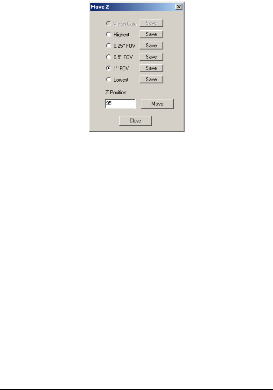
There is only one light and one view for X-Ray inspection: Side light and X-Ray View. There
are several FOV (field of view) choices for X-Ray inspection: 1”, 0.5” and 0.25” FOV.
NOTE
0.25” FOV is not available for X3 AXI system inspections.
For each FOV there are several X-Ray power levels. Each power level has its own X-Ray tube
voltage, current and spot size settings.
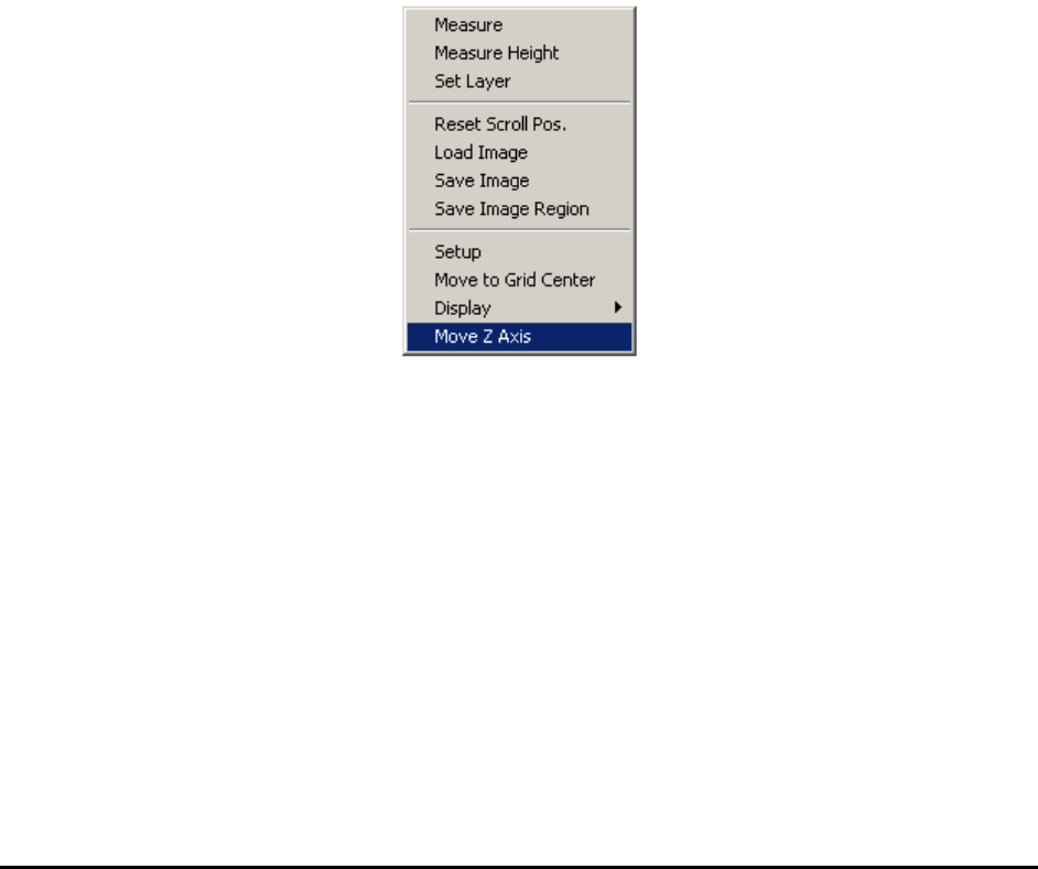
To change the FOV, press the right mouse button while pointing inside the Video area.
Select Move Z Axis to launch the Move Z dialog.
10-34 General Inspection Methodology
X-Ray Inspection for BGA device is also conducted in two processing steps: Preprocessing and
Decision. The Preprocessing step prepares the image and the Decision step determines the
Pass/Fail. The two steps use various machine vision algorithms to accomplish the task.
10.5.1 Preprocessing
Since X-Ray images are gray scale images, normally there is no preprocessing step needed for
inspection. The preprocessing step for X-Ray is defaulted to NONE.
NONE - No preprocessing (default)
Red Filter - Pass the image through red color filter.
Green Filter - Pass the image through green color filter.
Blue Filter - Pass the image through blue color filter.
Binarize - Binarize the image into two gray levels, black and white.