YesAX V3.1.2 - Software User Manual.pdf - 第262页
25 -2 Calibration and Verificat ion 25.4 Calibrate Stag e Linear Comp The Yes AX software compensates for mechanical imperfections of the XY camera transport mechanism. The software employs three scaling factors for comp…
Calibration and Verification 25-1
25 - Calibration and Verification
The software provides a comprehensive set of guided calibration procedures. Each procedure is
prompted by a dialog message that gives the instructions for the adjustment and lists the current
and the target values.
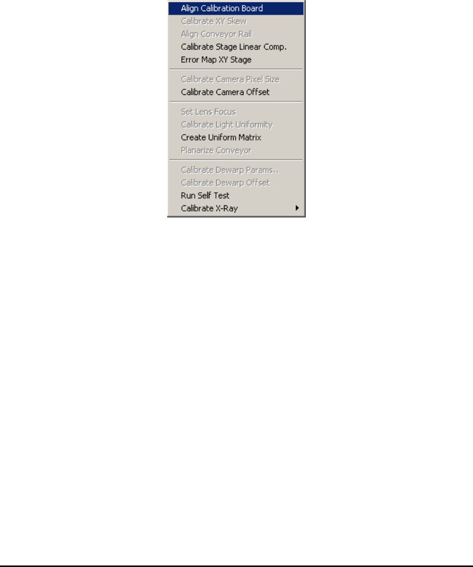
All the calibration procedures are launched from the Calibrate menu in the Builder mode.
The specialized calibration board (P/N 10876) is required for all calibrations and verifications.
The board must be properly aligned before any calibration begins.
25.1 Align Calibration Board
The Align Calibration Board is the procedure that guides the user through aligning the board in
the system. Upon starting the procedure the software opens the conveyor to the width of the
calibration board (approximately 559 mm wide). You may need to do some minor adjustments (1
or 2 mm) to the conveyor width for the calibration board to fit in. After the conveyor is opened to
the correct width, place the calibration board on the conveyor from the left opening and manually
push the board towards the center of the machine. Open the front door of the machine, reach in
with your hand and pull the calibration board further to the right so that it is over the hard stops.
The right edge of the calibration board should align approximately with the right limit sensor of
the X axis.
25.2 Calibrate XY Skew
This calibration adjusts the perpendicularity of the XY stage. The calibration involves removing
the top and side cover and the use of a special adjustment jig. This is a onetime adjustment. The
procedure is performed in the factory as part of the standard calibration procedure.
25.3 Align Conveyor Rail
This Align Conveyor Rail feature aligns the conveyor rail with the X axis. The software moves
between two points along the X axis, one on the left and the other on the right.

25-2 Calibration and Verification
25.4 Calibrate Stage Linear Comp
The YesAX software compensates for mechanical imperfections of the XY camera transport
mechanism. The software employs three scaling factors for compensation: X, Y, and Skew. The
X factor compensates for any linear error on the X axis that may be caused by inaccuracies of the
X lead screw. The Y factor compensates for linear error on the Y axis and the skew factor
compensates for imperfect XY orthogonality. The Calibrate Stage Linear Comp feature
calibrates these 3 compensation factors.
25.5 Error Map XY Stage
To compensate for non-linear distortion of the XY stage, the Error Map XY Stage feature
extends the error compensation features to include error mapping. The linear error compensation
mentioned earlier uses 3 scale factors to compensate for linear errors commonly found on an XY
stage. Error mapping compensates for all remaining errors by mapping it. Typically, error
mapping, when performed correctly, can increase stage accuracy by a factor of three.
Error mapping employs a grid (for example 27 x 24) of error correction factors. It maps the
distortion of the positioning system. The error correction of any given point is determined by
using a linear formula with the data from the 3 closest correction factors.
25.6 Calibrate Camera Angle
This Calibrate Camera Angle feature calibrates the angle of the top camera to have it aligned
with the X axis. During the procedure, the stage moves left and right to have the target cross on
the calibration board appear on the left and then right side of the field of view. If the camera
angle is correct, the video cross hair should align with the target cross in both positions. To
adjust camera angle, loosen the three small mounting screws (5/64 button head) that hold the
camera PCB to the mounting bar and rotate the camera PCB.
25.7 Calibrate Camera Pixel Size
This Calibrate Camera Pixel Size feature calibrates the pixel size of the top camera. The XY
stage encoder is used as a ruler. The pixel size is determined using the following formula:
Stage movement delta in um
Pixel Size in um = -----------------------------------
Pixel delta in count
To adjust the camera pixel size, raise or lower the camera by putting washers in the camera
mount. Raising the camera increases the pixel size.
Calibration and Verification 25-3
25.8 Self Test
The software provides a comprehensive set of self-testing features that automatically verify all
the essential calibration parameters. The self-test determines the current values of the calibration
items and then compares them with the corresponding specification values in the SysSpec.dat
file to generate a Pass or Fail status for each of the items. The Self Test feature takes the
guesswork out of the calibration.
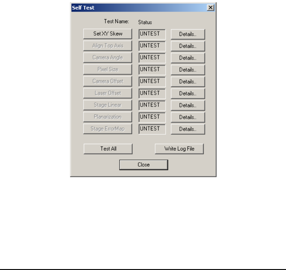
The self-test requires the specialized calibration board (P/N 10876) in the system. The board
must be properly aligned before any test can be preformed. The first item on the Self-Test dialog
“Set XY Skew” tests the alignment of the calibration board. The rest of the tests will be enabled
only if this test passes.
All the calibration procedures outlined in the previous section are performed in the factory as
part of the quality assurance program. It is unlikely for a machine to get out of calibration so bad
that it would require a complete re-calibration. The self test procedures that verify and correct the
system parameters are much more likely to be used by users or a field service engineer to bring a
machine back into specification.
The Self Test dialog lists a total of 9 tests. On the left is the action button for each individual test.
Clicking it starts the automated test procedure. The middle fields show the status of the tests. It
can be UNTEST, PASS or FAIL. The right buttons launch detailed dialogs that list the test
results. In many cases they also provide a means for the user to tweak the parameters to bring
them back into specification.
The Test All button runs all tests in sequence. The Write Log File button creates a log of the
current calibration session results.