YesAX V3.1.2 - Software User Manual.pdf - 第201页
A dvance Inspection Features 14 - 15 14.8 Logic Operation There is usually more than one inspection box used for inspecting any one part. With the Layer feature, you can even inspect the same area of the part with more t…
14-14 Advance Inspection Features
Setup the nominal distance from the reference point to the part, and establish an allowable
tolerance for each distance.
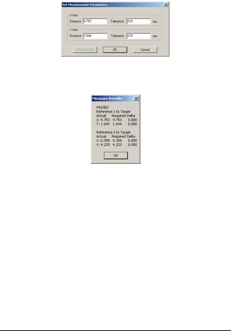
On the Set Measurement Parameters dialog for U1, pressing the Show Results button will
display the last measured distance for the part.
Running the Inspection Recipe
The measurement feature can be mixed with other inspection features in one recipe. An out of
tolerance measurement will result in the target part being flagged as ‘fail.’ It is added to the
review list for the operator to review just as any other part that failed the inspection.
Measurement Data Logging
When Track XY Position into ODBC database table is enabled in the Recipe Option dialog
box, the software will generate a text file logging the measured distance for each inspection
during inspection with measurement. The log file name is “MeasurePartPos.txt.” It is created in
folder C:\Aoi_Data\SPC_Datalog by default. The following is a fragment of the log file.
ETB001 Test REF1 4753 1644 REF2 6358 4220
ETB002 Test REF1 4753 1644 REF2 6358 4220
ETB003 Test REF1 4753 1644 REF2 6358 4220
ETB004 Test REF1 4753 1644 REF2 6358 4220
ETB005 Test REF1 4753 1644 REF2 6358 4220
The unit used in the text file is micron or um.

Advance Inspection Features 14-15
14.8 Logic Operation
There is usually more than one inspection box used for inspecting any one part. With the Layer
feature, you can even inspect the same area of the part with more than one inspection box. By
default, for the part to pass inspection, all the inspection boxes associated with it have to pass. In
other words, there is a logic AND relationship between the individual test results and the overall
test result. In some instances, you may want to use an OR relation between two or more
inspection boxes to achieve the desired inspection results.
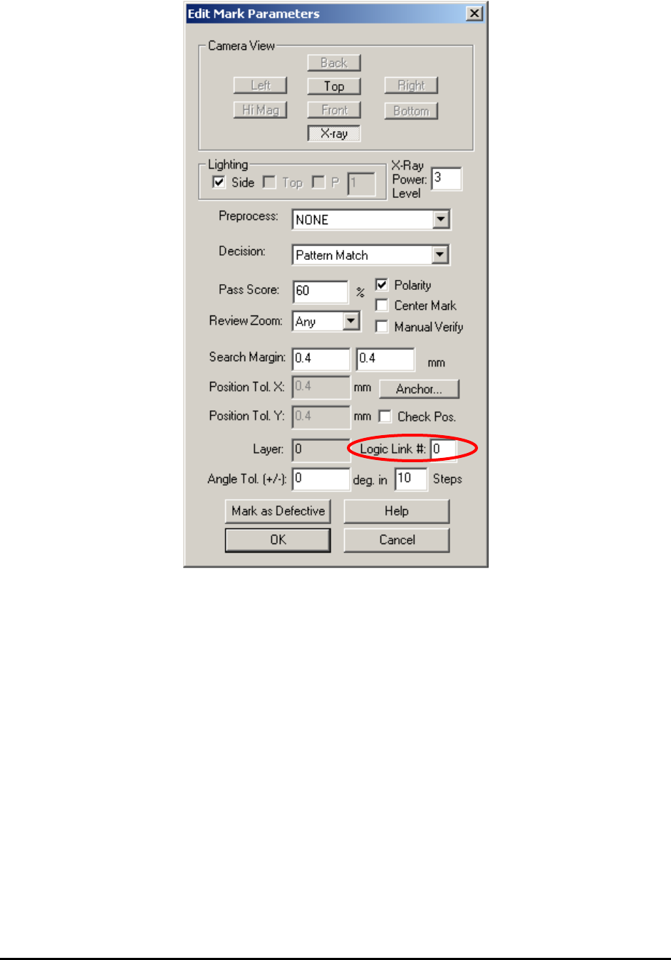
Use the Logic Link# feature to create an OR relation between two or more inspection boxes .
The logic link# is a number assigned to any inspection box (Marking, Lead or Solder). A number
0 disables the feature and any number from 1 to 9 establishes an OR link between the boxes with
the same number.
For example, you decide to use 3 marking boxes (M1, M2 and M3), 2 lead boxes (L1 and L2)
and 16 solder boxes (S1 to S16) in the inspection of a part. For the 3 marking boxes, M 1 has
Link#0, and M 2 and 3 have link# 1. The part inspection result equals:
Result = M1 AND (M2 OR M3) AND L1 AND L2 AND S1 AND S2 AND…
Use the Logic Link # field on the Edit Mark Parameters dialog to enter Link numbers.
14-16 Advance Inspection Features
14.9 Alternate Part Numbers
The Alternate Part Number feature is very different from the Alternate Template feature. The
Alternate Template feature is for dealing with parts of the same part number but have different
markings on them. The Alternate Part Number feature is used when a certain location (reference
designer) of a board allows more than one part number.
For example, a location allows a 100 Ohm 5%, 0805 resistor and may also allow a 101 Ohm, 1%,
0805 resistor. If only local libraries are used, it is possible (but not strictly correct) to handle the
situation using an alternate template. However, if the central library is being used, then using
alternate templates can create serious problems because the substitution may not be allowed on
other assemblies or locations. The Alternate Part Number feature should be used in this situation.