YesAX V3.1.2 - Software User Manual.pdf - 第199页
A dvance Inspection Features 14 - 13 The three parts in this measurement group (Reference 1, Targe t Part, and R eference 2) do not need to be in the same field of view. However, any one of the parts will need to be smal…
14-12 Advance Inspection Features
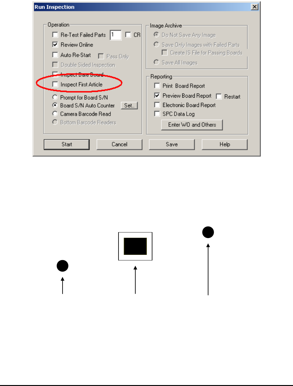
The last step is to indicate in the Run Inspection dialog whether the board being inspected is a
first article board or not.
Select File>Run Recipe from the Main Menu. The Run Inspection dialog opens.
For non-first article boards, the Inspect First Article checkbox should be un-checked.
14.7 Part Measurement Feature
This feature measures the part position relative to one or two reference points. For example, a
target part’s position needs to be determined relative to two reference marks.
Reference 1 Target Part Reference 2
Software determines the relative position from Reference 1 to Target Part and Reference 2 to
Target Part. Then it compares the relative distances to preset distances. If the difference between
the measured distance and the preset distance exceeds a predefined tolerance, a Fail status is
assigned to the target part; otherwise it is assigned a Pass status.
Advance Inspection Features 14-13
The three parts in this measurement group (Reference 1, Target Part, and Reference 2) do not
need to be in the same field of view. However, any one of the parts will need to be small enough
to fit into one field of view.
Setup for Measurement
To setup a recipe for measuring target part position as described above, train 3 separate parts and
add them into the recipe.
For example if the target part has a reference designator as U1.
Target Part -U1
Reference 1 -U1_REF1
Reference 2 -U1_REF2
For each part, train a Marking inspection box that will locate the position of the part. The
decision algorithm can either be Pattern Match or Edge Locator. Pattern Match is easy to setup
but is less accurate (about 1 pixel). Edge Locator is more accurate (about ¼ pixel) but will
require two inspection boxes to locate both horizontal and vertical edges.
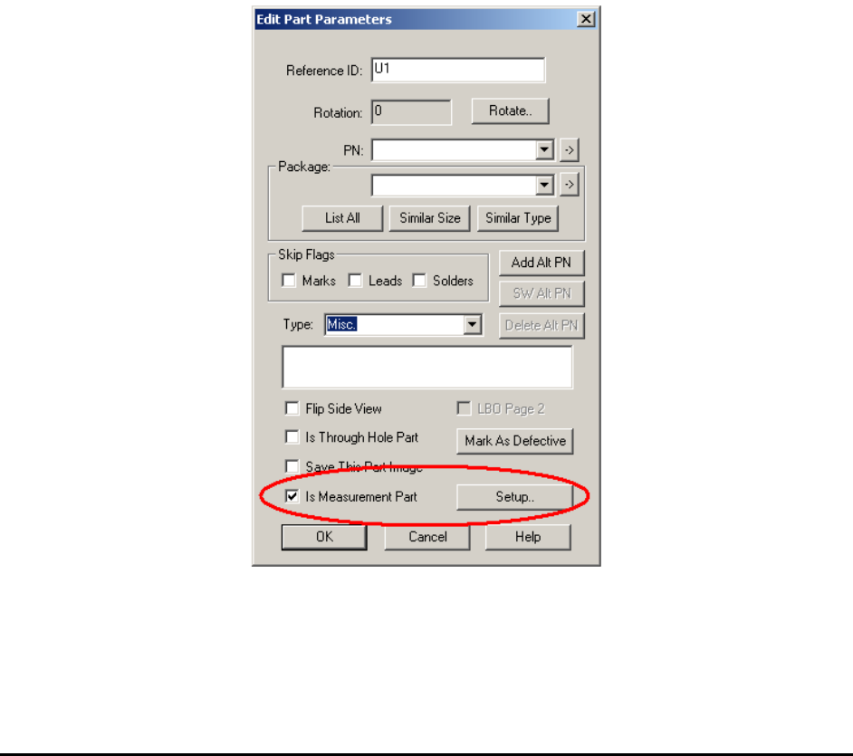
For each part, edit the part’s parameter and check the Is Measurement Part checkbox in the
Edit Part Parameters dialog.
For U1_REF1 and U1_REF2, press the Setup button on the right and launch the Set
Measurement Parameters dialog box.
14-14 Advance Inspection Features
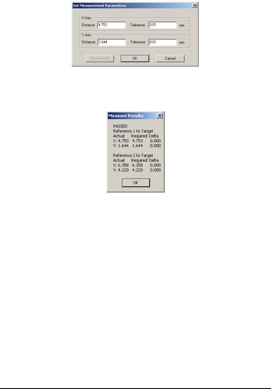
Setup the nominal distance from the reference point to the part, and establish an allowable
tolerance for each distance.
On the Set Measurement Parameters dialog for U1, pressing the Show Results button will
display the last measured distance for the part.
Running the Inspection Recipe
The measurement feature can be mixed with other inspection features in one recipe. An out of
tolerance measurement will result in the target part being flagged as ‘fail.’ It is added to the
review list for the operator to review just as any other part that failed the inspection.
Measurement Data Logging
When Track XY Position into ODBC database table is enabled in the Recipe Option dialog
box, the software will generate a text file logging the measured distance for each inspection
during inspection with measurement. The log file name is “MeasurePartPos.txt.” It is created in
folder C:\Aoi_Data\SPC_Datalog by default. The following is a fragment of the log file.
ETB001 Test REF1 4753 1644 REF2 6358 4220
ETB002 Test REF1 4753 1644 REF2 6358 4220
ETB003 Test REF1 4753 1644 REF2 6358 4220
ETB004 Test REF1 4753 1644 REF2 6358 4220
ETB005 Test REF1 4753 1644 REF2 6358 4220
The unit used in the text file is micron or um.