00194081-01.pdf - 第107页
User Manual SIPLAC E CF 4 Setting up the placement system Software Version SR.408.xx 03/2006 US Edition 4.1 Transport configuration and infrastructure 107 4 Setting up the placement system 4.1 T ra nsport co nfigur ation…
3 Technical data User Manual SIPLACE CF
3.12 Magnetic pin support Software Version SR.408.xx 03/2006 US Edition
106
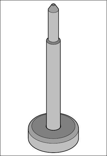
3.12 Magnetic pin support
Item no. 00119680-xx
Wide boards tend to deflect during placement such that, under certain circumstances, the compo-
nents can no longer be placed with the desired accuracy. Highly curved PCBs also affect the
placement accuracy. This problem can be easily rectified by fitting magnetic pin supports on the
lifting table.
3
Fig. 3.12 - 1 Magnetic pin support
User Manual SIPLACE CF 4 Setting up the placement system
Software Version SR.408.xx 03/2006 US Edition 4.1 Transport configuration and infrastructure
107
4 Setting up the placement system
4.1 Transport configuration and infrastructure
4
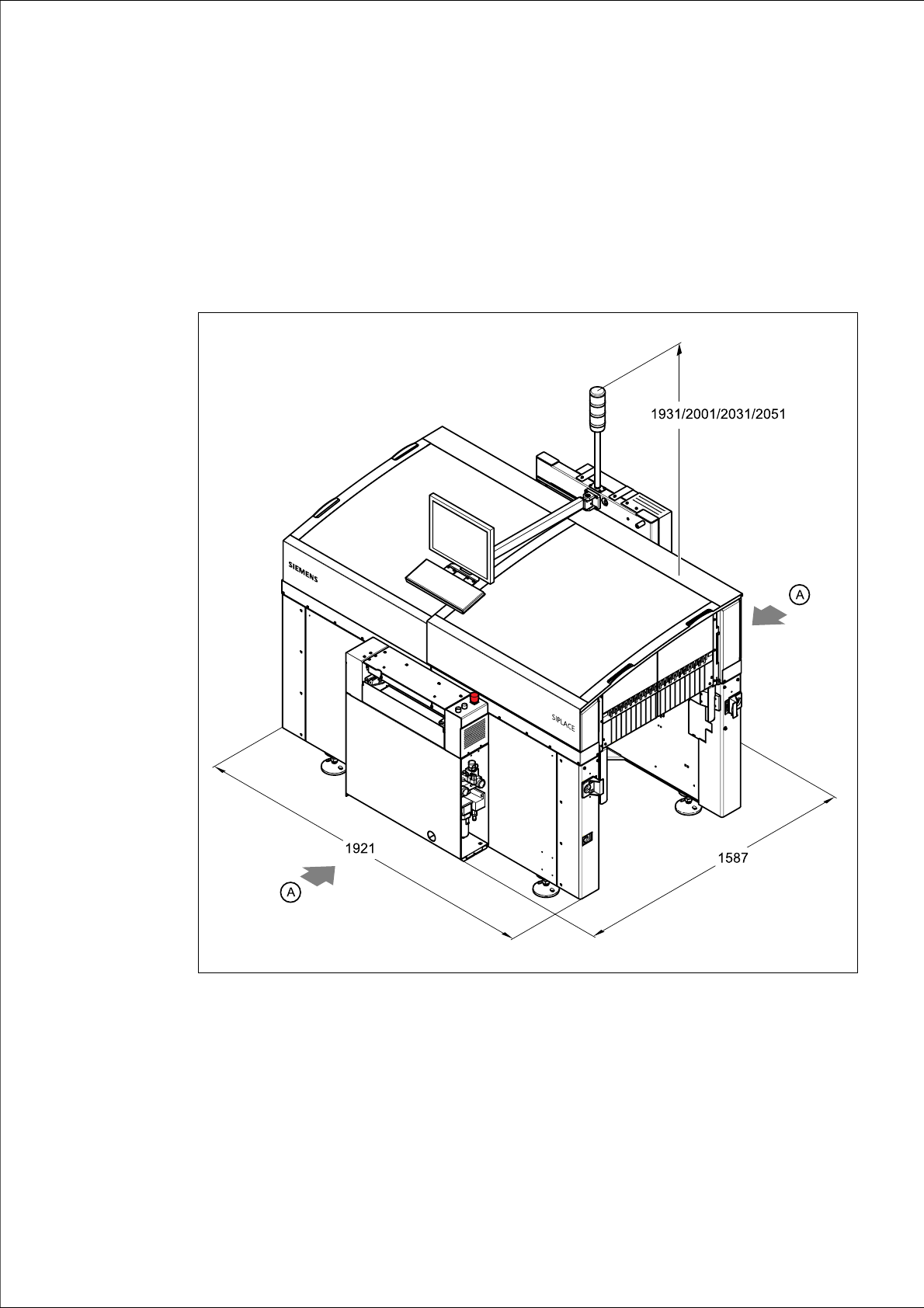
Fig. 4.1 - 1 Dimensions of the placement system during transportation and setting up in millimeters
4
(A) Points for attaching the fork-lift truck (fork length 1600 mm)
(1) Input conveyor
(2) Output conveyor

4 Setting up the placement system User Manual SIPLACE CF
4.1 Transport configuration and infrastructure Software Version SR.408.xx 03/2006 US Edition
108
The standard PCB conveyor height is 830 mm 15 mm. The standard overall height of the
machine is 1931 mm. For a PCB conveyor height of 950 mm (SMEMA option), this gives an
overall height of 2051 mm.
4.1.1 Transport configuration
The following components are not installed when the placement system is delivered from the fac-
tory:
– Keyboard
–Monitor
– Indicator lamp
– Component trolley
– Component barcode reader
4.1.2 Safety instructions
WARNING
Æ The applicable accident prevention regulations concerning the transportation of heavy goods
must be followed.
Æ In particular, you should wear safety boots to minimize the risk of crushing your feet.
Æ When you are transporting the machine, make sure that all the feet are clear of the floor. If they
are not clear, the feet will drag along the floor and bump into obstacles. This could damage the
machine foot thread in the machine frame.
Æ Attach the pallet jack only at the points identified by (A) in Fig. 4.1 - 1).
4.1.3 Means of transport
Use a pallet jack with the following specification to carry the machine:
Fork length: min. 1800 mm
Carrying power: min. 2000 kg
Clear width between forks: min. 350 mm 4