00194081-01.pdf - 第72页
3 Technical data User Manual SIP LACE CF 3.4 Dimensions and weight of the placement sys tem Software Version SR. 408.xx 03/2006 US Edition 72 3.4 Dim ensions and weight of the placement system 3.4.1 Dimensi ons of the pl…

User Manual SIPLACE CF 3 Technical data
Software Version SR.408.xx 03/2006 US Edition 3.3 Technical data – ratings
71
3.3 Technical data – ratings
3.3.1 Technical data – electrical ratings
3
3.3.2 Technical data – compressed air supply
3
3.3.3 Technical data – compressed air specification
Maximum particle size by density, based on ISO/DIS 8573-1 (class 1)
3.3.4 Technical data – noise emissions
3
3.3.5 Technical data – permissible ambient factors
3
Supply voltage 3 x 400 VAC ± 5 %; 50/60 Hz (Europe)
3 x 208 VAC ± 5 %; 50/60 Hz (U.S.A.)
3 x 200 VAC ± 5 %; 50/60 Hz (Japan)
Fuses 3 x 16 A (3 x 400 VAC, 3 x 208 VAC, 3 x 200 VAC)
Nominal apparent power 1,3 kVA
Rated current consumption 3.4 A / 3 x 400 VAC
Power failure Max. 20 msec
Compressed air pressure Min. 0.55 MPa (5.5 bar) to 1.0 MPa (10 bar), ½"-connection
Compressed air consumption 400 Nl/min.
Operating pressure Set to 0.52 MPa (5.2 bar)
Particle size 0.1 µm
Particle density 0.1 mg/m³
Maximum oil content (class 1) Particle density 0.01 mg/m³
Pressure dewpoint (class 4) Dewpoint +3°
Max. noise emissions 74dB(A)
Room temperature Between 15°C and 35°C
Atmospheric humidity 30 to 80%
(but no higher than 45% on average in order to prevent any
possibility of condensation on the machine).
3 Technical data User Manual SIPLACE CF
3.4 Dimensions and weight of the placement system Software Version SR.408.xx 03/2006 US Edition
72
3.4 Dimensions and weight of the placement system
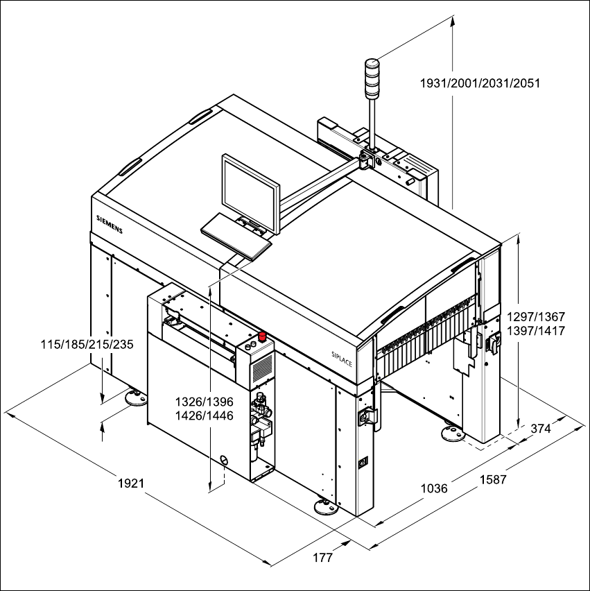
3.4.1 Dimensions of the placement system
3
Fig. 3.4 - 1 Dimensions of the placement system in millimeters
User Manual SIPLACE CF 3 Technical data
Software Version SR.408.xx 03/2006 US Edition 3.4 Dimensions and weight of the placement system
73
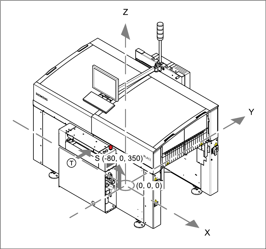
3.4.2 The placement system’s center of gravity
3
Fig. 3.4 - 2 The placement system’s center of gravity
3
X coordinate - 80 mm
Y coordinate 0 mm
Z coordinate 350 mm high
T PCB transport direction
These center of gravity coordinates relate to placement systems with a PCB transport height of
830 mm.