00194081-01.pdf - 第173页
User Manual SIPLAC E CF 6 Component han dling Software Vers ion SR.408.xx 03/2006 US Ed ition 6.5 Waffle-pack c hanger 173 6.5.6 Safety equipment EMERGENCY STOP button The enti re system , i.e. SIP LACE CF a nd waffle-pa…
6 Component handling User Manual SIPLACE CF
6.5 Waffle-pack changer Software Version SR.408.xx 03/2006 US Edition
172
6.5.5 Controls and displays
The EMERGENCY STOP button and the switch for changing the speed are located on the back
of the waffle-pack changer.
Slow key
It is possible to reduce the speed for waffle-pack trays with small components that could fall out
of their pockets if the tray is traveling quickly.
Press the Slow key.
All the waffle-pack trays travel at a slower speed.
EMERGENCY STOP button
Press the EMERGENCY STOP button. The power supply is switched off and the entire system
stops.
6
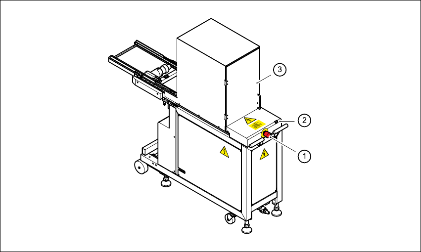
Fig. 6.5 - 5 WPC - controls
6
(1) EMERGENCY STOP button
(2) "Slow" key
(3) Safety doors

User Manual SIPLACE CF 6 Component handling
Software Version SR.408.xx 03/2006 US Edition 6.5 Waffle-pack changer
173
6.5.6 Safety equipment
EMERGENCY STOP button
The entire system, i.e. SIPLACE CF and waffle-pack changer, is stopped immediately.
You can then either continue or cancel placement. Check whether there are any incomplete
PCBs remaining.
Safety doors
When the safety doors are opened, the power to the waffle-pack changer is switched off and the
sequence of waffle-pack changer functions stops. It resumes its functions when the safety doors
are closed.
CAUTION 6
Do not open the safety doors of the waffle-pack changer while it is picking up a component. 6
6.5.7 Installing the waffle-pack changer
Æ Before you push the waffle-pack changer into the placement machine, remove the top part of
the fine pitch camera.
CAUTION DANGER OF TIPPING 6
The waffle-pack changer runs on wheels. However, these are only suitable for short distances, i.e.
for docking in and out of the placement machine. Given the danger of tipping, use a suitable pallet
jack for longer distances (item no. 00123141-01). 6
Æ Carefully push the WPC into location 1 on the machine. The docking pins of the WPC must
protrude over the docking grooves in the SIPLACE CF.
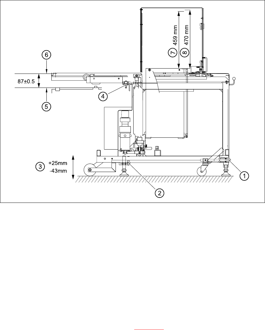
Æ Check the measurement (87 +/- 0.5 mm) from the bottom edge of the magazine carrier to the
top edge of the component feeder table (see Fig. 6.5 - 6
).
6 Component handling User Manual SIPLACE CF
6.5 Waffle-pack changer Software Version SR.408.xx 03/2006 US Edition
174
6
Fig. 6.5 - 6 Setting up the WPC
6
(1) Using UP/DOWN Allen key
(2) Clamping screw
(3) Stroke
(4) Docking pin
(5) Top edge of component feeder table magnetic rail
(6) Bottom edge of magazine carrier
(7) Nominal travel (459 mm)
(8) Refill position (470 mm)
6
Æ Loosen the clamping screws on the feet (see Fig. 6.5 - 6) and use a 10 mm ball-tip Allen key
to turn the WPC down until docking pin engages. At the same time, align the WPC using the
machine's integral spirit level.
Æ Tighten the clamping screws and check the machine spirit level again.
Æ Place the top part of the camera on the component vision module once more.