00194081-01.pdf - 第192页
7 Station extensions User Manual S IPLACE CF 7.5 Multicolor PCB camera (type 18) Software Version S R.408.xx 03/2006 US Edition 192 7.5 Multicolor PCB camera (type 18) 7.5.1 Gener al As an opti on, a m ulticolor PCB cam …

User Manual SIPLACE CF 7 Station extensions
Software Version SR.408.xx 03/2006 US Edition 7.4 DCA vision camera
191
7.4.3 Description
The 6-segment Collect&Place head can optically center and place component sizes from 0.6x
0.3mm² to 13 x 13 mm² using the DCA vision module. The DCA package optimizes the speed
and accuracy when placing high-speed flip-chips and bare die components. 7
7.4.4 Technical data - 6-segment Collect&Place head with DCA camera
Component range 0201 up to 13 mm x 13 mm
Component specification
Max. height
Min. lead pitch
Min. bump pitch
Min. ball/bump diameter
Min. dimensions
Max. dimensions
Max. weight
6 mm
0.4 mm
0.2 mm
0.11 mm
0.6 mm x 0.3 mm
13 mm x 13 mm
2 g
Programmable set-down force 2.4 to 5.0 N
Nozzle types 9 xx
Max. placement rate 9,000 comp/h
Angular accuracy ± 0.5° / 3 σ ± 0.7° / 4 σ
Placement accuracy ± 68 µm / 3 σ ± 90 µm / 4σ
7 Station extensions User Manual SIPLACE CF
7.5 Multicolor PCB camera (type 18) Software Version SR.408.xx 03/2006 US Edition
192
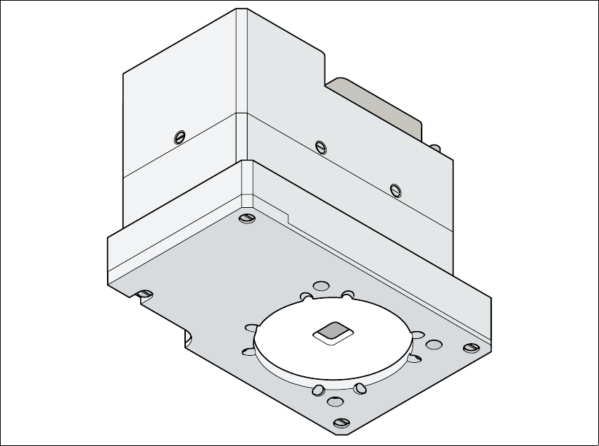
7.5 Multicolor PCB camera (type 18)
7.5.1 General
As an option, a multicolor PCB camera can be installed in place of the sub-gantry camera. The
multicolor PCB camera offers four different types of illumination. This greatly increases fiducial de-
tection and thus the centering accuracy.
7
Fig. 7.5 - 1 Multi-color PCB camera
7.5.2 Type of illumination
The following types of illumination can be selected on the multicolor PCB camera:
– Standard lighting
This mixture of white and infrared lighting can be used to detect a broad range of fiducials.
The image contrast can be improved by varying the illumination, thus optimizing the centering
of different fiducials.
User Manual SIPLACE CF 7 Station extensions
Software Version SR.408.xx 03/2006 US Edition 7.5 Multicolor PCB camera (type 18)
193
– White lighting
This type of illumination is used for standard PCBs with tinned fiducials.
– Blue oblique lighting
In most cases, this can be used to greatly improve the contrast with bright fiducials on a light
base material, such as ceramic or CEM. Fiducials covered with solder resist can also be de-
tected better on a light background.
– Infrared lighting
This type of illumination is particularly useful for fiducials that are covered with solder resist
or for fiducials on flex materials. It is also sometimes possible to improve detection of silver/
platinum fiducials on ceramic. This should be tested by carrying out a test centering or place-
ment run.