00194081-01.pdf - 第186页
7 Station extensions User Manual S IPLACE CF 7.3 Coplanarity laser module Software Version SR.408.xx 03/2006 US E dition 186 7.3.3 Safety inst ructions DANGER NEVER mod ify or b ypass safety devices on the co planar ity …

User Manual SIPLACE CF 7 Station extensions
Software Version SR.408.xx 03/2006 US Edition 7.3 Coplanarity laser module
185
The coplanarity laser module is combined with optical component centering, and is used in a
vision module. Components with bent or missing leads are detected and disposed of, if neces-
sary.
7.3.2 Technical data
Component range: Can be used for gull wing components, pitch > 0.3
The component size and lead pitch are limited by the component
position detection system, i.e. max. size 43.0 mm x 43.0 mm x
11.0 mm.
Measuring principle: Contact-free measurement by laser triangulation
Algorithm functions: JEDEC standard - calculation of the placement plane; all deviations
are determined in relation to this plane. If the component is angled
with respect to the vacuum nozzle, as can happen if an adapter is
used, then it will have no influence over the choice between ‘good’
and ‘bad’.
Output: < 5 mW
Measuring range: ± 2,5 mm
Laser focus: Elliptical, 50 µm x 95 µm
Thermal stability: ± 1 μm/K
Wave length: 670 nm
Resolution: 0,25 µm
Scanning frequency: 10 kHz
Weight: 500 g
Operating temperature: 0°C ... 40
Atmospheric humidity: 5 - 95 % non-condensing
Ambient pressure: Atmospheric pressure
Vibration: As per IEC 68-2-6
Mechanical shock: As per IEC 68-2-27
EMC: As per EN 50081-2 emitted interference
As per EN 50082-2 immunity to interference
Degree of protection: IP 64
Mech. dimensions: 118 mm x 30 mm x 125,5 mm
Permissible ambient light: 30.000 lx
Safety: The coplanarity laser module conforms to laser class 1, when
installed in the machine. The module will not work when off the
machine unless further devices are installed or the protective
functions are modified. If the protective functions on the device are
bypassed, the machine automatically conforms to
laser class 3B - Risk of injury to eyes and skin
-
and thus requires protective measures to VBG 93.
7 Station extensions User Manual SIPLACE CF
7.3 Coplanarity laser module Software Version SR.408.xx 03/2006 US Edition
186
7.3.3 Safety instructions
DANGER
NEVER modify or bypass safety devices on the coplanarity laser module! 7
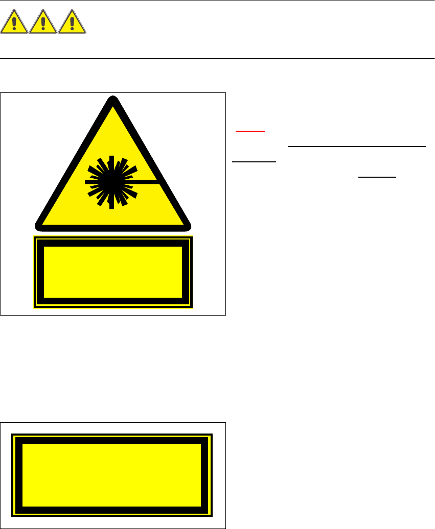
With no protective measures, the coplanarity
laser module conforms to laser class 3B
(7.3 - 2
)
This means there is a risk of injury to eyes
and skin!
For this reason, you should NEVER
bypass the safety devices!
Fig. 7.3 - 2 Identification for laser class 3B
The following safety devices must be installed on the machine if the laser module is to be oper-
ated in laser class 1 without risk to the eyes and skin:
The interlock line is connected in series with
the switches for the protective hood. This
protective function is maintained even if the
key switch is turned to bypass the protection.
This means that the laser module can only
be used if the machine is closed!
Fig. 7.3 - 3 Identification for laser class 1
Invisible laser radiation
Do not expose the beam
Class 3 B Laser Product
1mW max., 670nm; n. IEC 825-1(1993)
Laser class 1

User Manual SIPLACE CF 7 Station extensions
Software Version SR.408.xx 03/2006 US Edition 7.3 Coplanarity laser module
187
DANGER
The safety guarantee is automatically invalidated if safety devices are modified or bypassed!
The user must also conform to the guidelines issued by the umbrella organization of employers'
liability insurance associations – VBG 93 – i.e
- Registration with the employers’ liability insurance association
- Appointment of a laser protection officer
- Drawing up guidelines for use of the module 7
7.3.4 Overview
7.3.4.1 Analysis unit
The coplanarity laser module consists of two components: the analysis unit with its control sec-
tion, and the laser module. The analysis unit is located in the control unit (see Fig. 7.3 - 4
). The
operating state is indicated by three green LEDs on the front panel of the analysis unit:
7
Press the RESET key to initialize the coplanarity laser module.
7.3.4.2 Laser module
The laser module is fixed to a supporting frame on the right-hand side of the machine (see Fig.
7.3 - 5
).
Two red LEDs and one green LED signal the operating states of the laser module:
LED (see 7.3 - 4) On Off
1 green 5 operating voltage No voltage
2 green 12V operating voltage No voltage
3 green Laser module in use Laser module switched off
LED (see Fig. 7.3 - 5) On Off
4 red OUT OF RANGE
(outside the measuring range)
–
5 red POOR TARGET
(component is insufficiently reflective)
–
6 green Laser module in use Laser module switched off