00198365-03_UM_JTF-ML2_TX12_V1-V2_EN.pdf - 第36页
4 Setting up and commissioning 4.2 Retrofitting in the SIPLACE TX-Series 36 User Manual SIPLACE TX V1/V2 Series JEDEC Tray Feeder (JTF-ML2) 11/2019 Fig.48: Fitting the rear cover SIPLACE TX-Series V1 ► Fasten the rear c…
4 Setting up and commissioning
4.2 Retrofitting in the SIPLACE TX-Series
User Manual SIPLACE TX V1/V2 Series JEDEC Tray Feeder (JTF-ML2) 11/2019 35
Fig.44: Removing the empty tape duct
► Remove the two screws (2) holding the
empty tape duct (1).
► Carefully lift the empty tape duct out of
the COT insert.
Fig.45: Dismantling the sensor
► Dismantle the sensor(1) on the right
NC holder.
► Dismantle the vacuum hose and extend
it with the adapter assembly nozzle sta-
tion TX V2 [03169973—xx] (2).
► This is necessary if a CPP head and
the big reject bin with nozzle station are
installed.
Fig.46: Dismantling the rear cover
► Remove the three screws(1) fastening
the rear cover(2).
Now, you can move the cover a bit to the
side and lift it off. Thus, it is easier to thread
the sensor cable.
Fig.47: Converting the sensor
► Push the sensor through the open-
ing(1) on the front cover.
4 Setting up and commissioning
4.2 Retrofitting in the SIPLACE TX-Series
36 User Manual SIPLACE TX V1/V2 Series JEDEC Tray Feeder (JTF-ML2) 11/2019
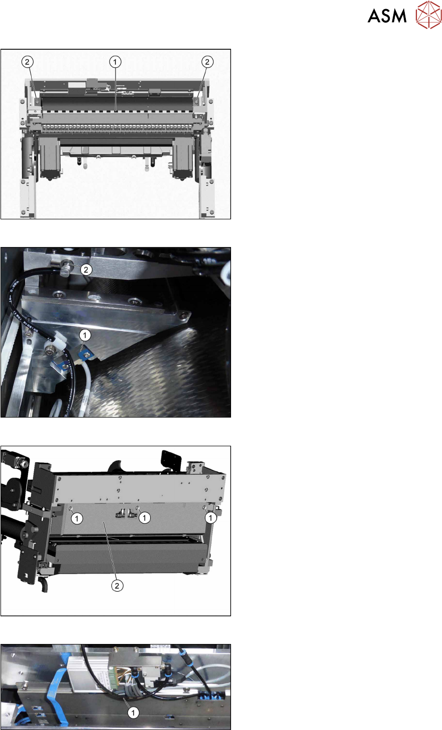
Fig.48: Fitting the rear cover
SIPLACE TX-Series V1
► Fasten the rear cover(2) with three
screws(1).
The sensor cable is run through the
opening(3) in the cover.
CAUTION!
Make sure not to clamp any hoses or
cables.
.
Fig.49: Fitting the rear cover
SIPLACE TX-Series V2
Fitting the reject bin holder with nozzle station for the SIPLACE TX Series V1
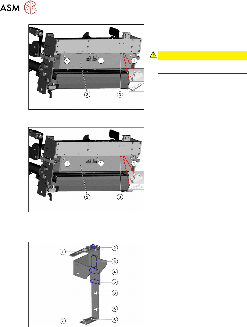
Fig.50: Fitting the reject bin holder
1. Nozzle station [03090348‑xx]
The nozzle station is fitted after meas-
uring the height.
2. Fastening screws of the nozzle station
[00333782‑xx]
3. Fastening screws for retaining bracket
ISO10642-M5x10-A2-70 [03082832‑xx]
4. Fastening screws of the complete
holder on the COT insert DIN7984-
M6x12-A2-70 [03081847‑xx]
5. Fastening screws ISO 7380-2 M 3 x 6-
A2-70 [03099571-xx], only for setting
the sensor height
6. Three lugs for cable ties
7. Sensor [03088550‑xx]
The sensor that is already installed and
cabled on the insert is used.
► Fit the individual parts of the reject bin holder.
► Use the cable ties to fix the sensor to the three lugs.
4 Setting up and commissioning
4.2 Retrofitting in the SIPLACE TX-Series
User Manual SIPLACE TX V1/V2 Series JEDEC Tray Feeder (JTF-ML2) 11/2019 37
Fig.51: Fitting the reject bin holder
► Fit the reject bin holder with two fasten-
ing screws DIN7984-M6x12-A2-70
[03081847-xx](1) on the COT insert.
Push the sensor cable behind the cover
as far as possible.
CAUTION!
If too much cable length lies in front of
the cover, the reject bin may damage
the cable.
.
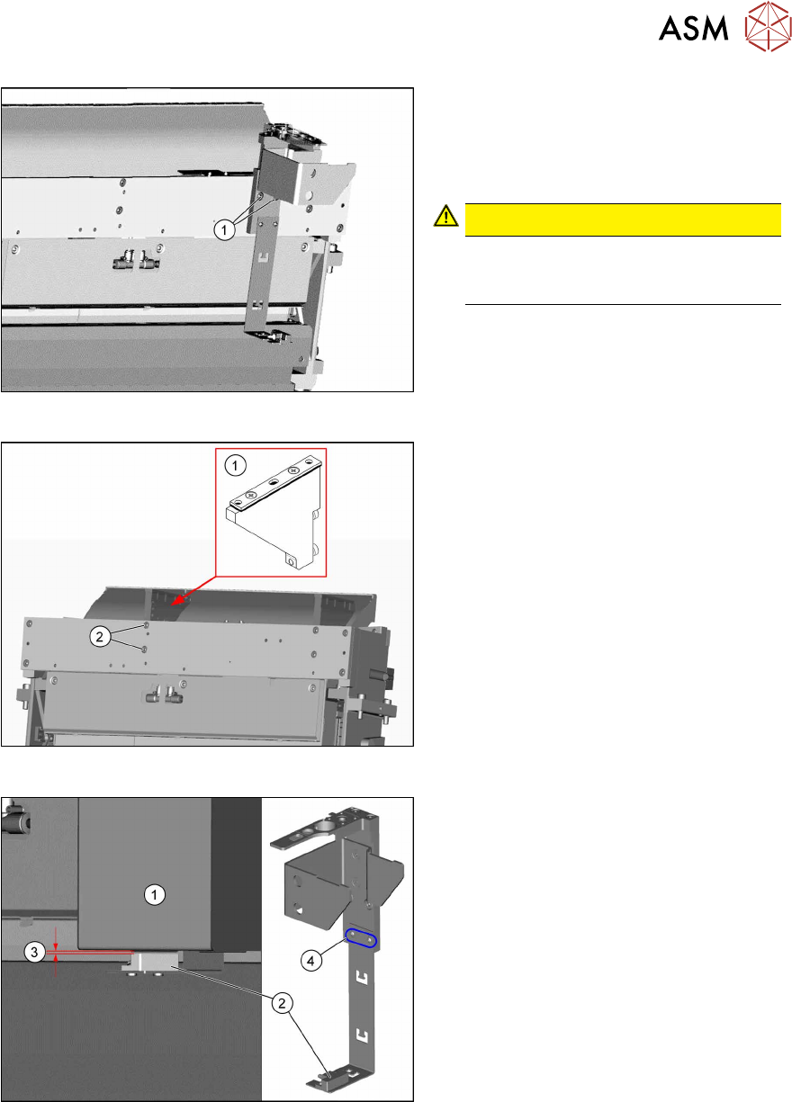
Fig.52: Fitting the NC holder
► Fit the right NC holder(1) with two
fastening screws DIN 7984-M6 x 12-
A2-70 [03081847-xx](2). The right NC
holder is replaced by the supplied ver-
sion without nozzle station.
Do not fit the NC and the nozzle station yet!
Fig.53: Setting the sensor
1. Reject box
2. Sensor
3. Distance 2.0+/-1.0mm
4. Fastening screws for setting the senor
height
► Insert the reject bin.
► Set the sensor to a distance of
2.0+/-1.0mm from the reject bin.