00198365-03_UM_JTF-ML2_TX12_V1-V2_EN.pdf - 第41页
4 Setting up and commissioning 4.2 Retrofitting in the SIPLACE TX-Series User Manual SIPLACE TX V1/V2 Series JEDEC Tray Feeder (JTF-ML2) 11/2019 41 Fig.62: Fitting the NC holder ► Fit the two NC holders (2) , with two …
4 Setting up and commissioning
4.2 Retrofitting in the SIPLACE TX-Series
40 User Manual SIPLACE TX V1/V2 Series JEDEC Tray Feeder (JTF-ML2) 11/2019
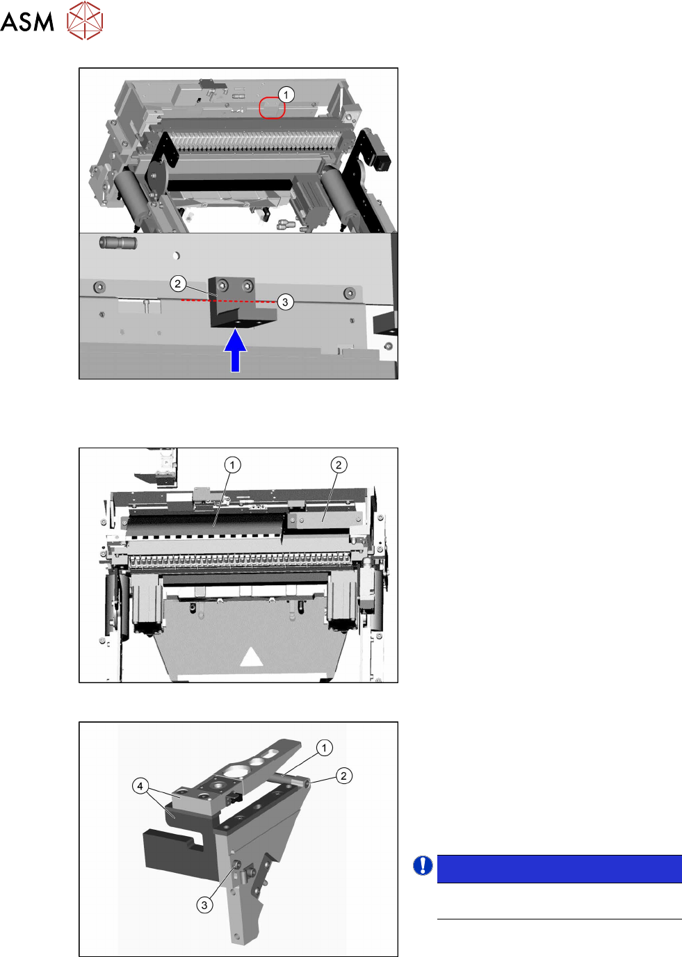
Fig.59: Fitting the holder
► Fit the holder(2), using the two screws
ISO4762-M6x14-A2-70 [03043125‑xx]
provided, to the traverse bar(1).
When tightening the screws, press the
holder upwards, against the edge(3).
Fitting the empty tape duct and removing the nozzle changer
Fig.60: Fitting the empty tape duct and cover
► Fit the short empty tape duct(1), using
two ISO4762-M6x14-A2-70
[03043125‑xx] screws.
► Fit the "hand guard tape cutter"(2)
[03130649‑xx] with two screws
ISO4762-M6x14-A2-70 [03043125‑xx].
Fig.61: Removing the NC holder
Perform the following steps on the dis-
mantled NC holder:
► Remove the screw(2) fastening the
support(1) and remove this.
► Remove the screw(3) fastening the
nozzle station and the reject bin
holder(4) and remove this.
NOTICE!
The previously used nozzle station is
no longer needed.
.
► Close open pneumatic connections if
necessary.
4 Setting up and commissioning
4.2 Retrofitting in the SIPLACE TX-Series
User Manual SIPLACE TX V1/V2 Series JEDEC Tray Feeder (JTF-ML2) 11/2019 41
Fig.62: Fitting the NC holder
► Fit the two NC holders(2) , with two
screws in each case(1).
Do not fit the NC yet.
4.2.5.3 Converting the machine protection
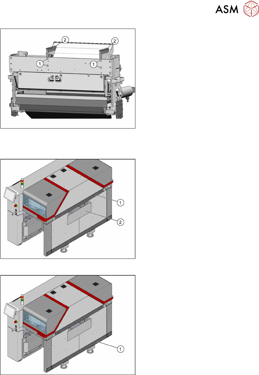
Fig.63: Removing the hand guard
1. Top rail with top hand guard below it
2. Bottom hand guard
► For removal of the following parts, read
the relevant section in the Assembly In-
structions "Input and Output Conveyor
Extension SIPLACE
TX" [00198141‑xx].
Fig.64: Removing the bottom rail
► Remove the bottom rail(1).
4 Setting up and commissioning
4.2 Retrofitting in the SIPLACE TX-Series
42 User Manual SIPLACE TX V1/V2 Series JEDEC Tray Feeder (JTF-ML2) 11/2019
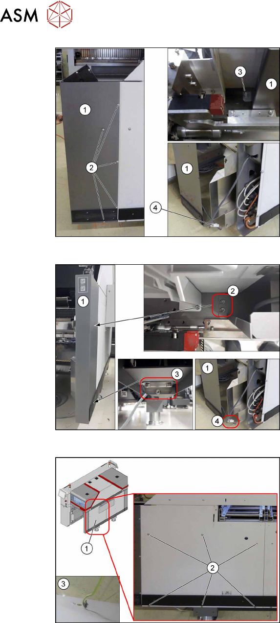
Fig.65: Removing the corner cover on the SIPLACE TX V1
SIPLACE TX V1:
Remove the corner cover(1). To do so, pro-
ceed as follows:
► Remove the screws(2) on the outer
side.
► Remove the screw(3) on the inner
side.
Hold the corner cover firmly while doing
this, so that it does not accidentally fall
down.
► Unplug the connector(4) and place the
corner cover(1) to one side.
Fig.66: Removing the corner cover on the SIPLACE TXV2
SIPLACE TX V2:
Remove the corner cover(1). To do so, pro-
ceed as follows:
► Remove the screws(2) on the inner
side.
► Remove the screws(3) on the bottom
side.
Hold the corner cover firmly while doing
this, so that it does not accidentally fall
down.
► Unplug the connector(4) and place the
corner cover(1) to one side.
Fig.67: Removing the standard side cover on the SIPLACE
TXV1/V2
► Remove the six screws(2) fastening
the standard side cover(1).
Hold the standard side cover firmly
while doing this, so that it does not ac-
cidentally fall down.
► Loosen the ground cable(3) on the
back of the standard side cover and
place it to one side.