00198365-03_UM_JTF-ML2_TX12_V1-V2_EN.pdf - 第92页
7 Appendix 7.1 Excerpts from the Service Manual 92 User Manual SIPLACE TX V1/V2 Series JEDEC Tray Feeder (JTF-ML2) 11/2019
7 Appendix
7.1 Excerpts from the Service Manual
User Manual SIPLACE TX V1/V2 Series JEDEC Tray Feeder (JTF-ML2) 11/2019 91
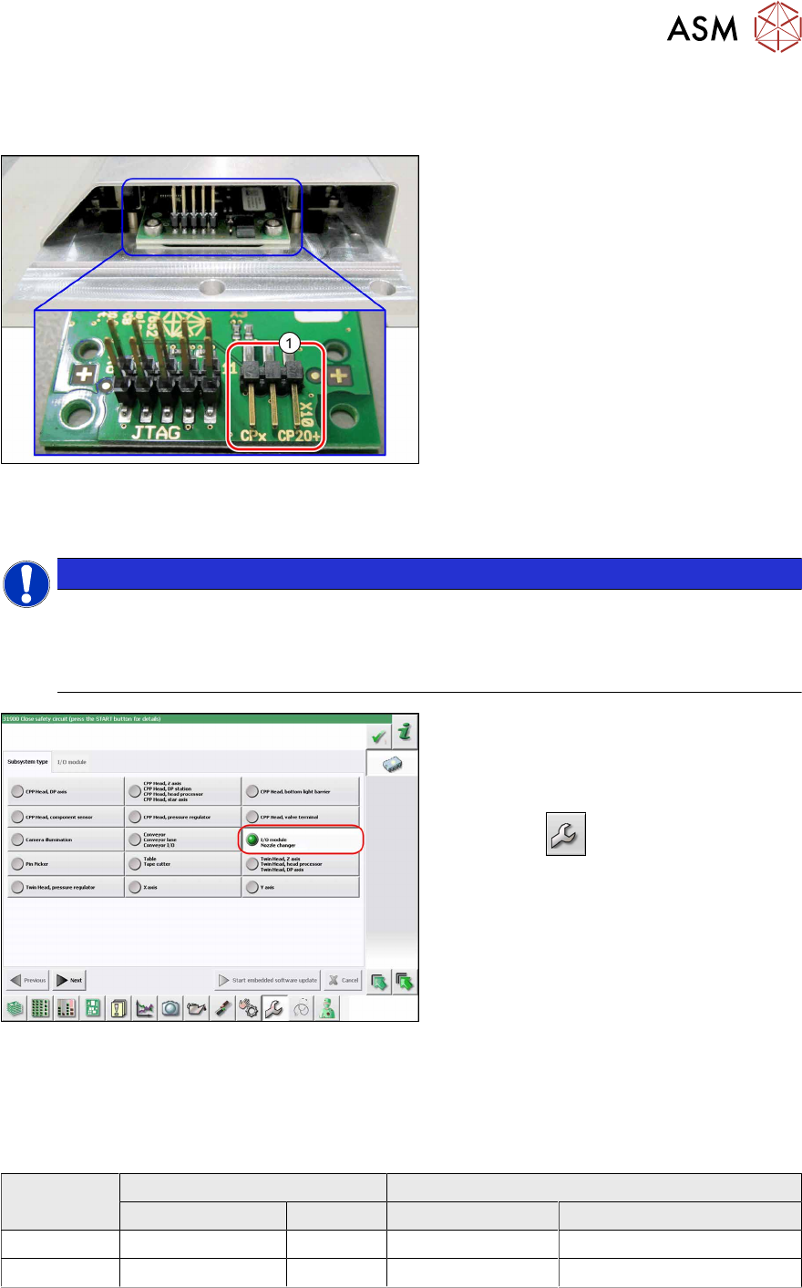
7.1.2.3 Jumpers on the Nozzle Changer
Overview
Fig.162: Jumpers on the nozzle changer
1. Jumper X10
The jumper X10 needs to be set at the fol-
lowing nozzle changers:
●
Nozzle changer basic structure
CPx - short assembly [03147925‑xx]
(replaces [03103649‑xx],
[03062463‑xx])
●
Nozzle changer basic structure
CPx – long assembly [03147324-xx]
●
Nozzle changer basic structure
CPx – long assembly [03103514-xx]
Preparation
NOTICE
Before installation
Due to the design, this setting must be performed before installation in the machine.
► If the new nozzle changer is being fitted as a spare part in a machine with I/O module
control, you will need to reconnect the jumper to pin 1-2.
Fig.163: Checking the I/A module control
To check whether the machine has I/O mod-
ule control, proceed as follows:
► Switch over to the operator level Ser-
vice.
► Click the
button.
► Click on the Embedded software but-
ton.
► Click the Update subsystem button.
► If an I/O module control is present, you
will see the entry Nozzle Changer at I/
O Module.
Adjustment
► Set the correct value on the jumper for your head type, software and control method.
Jumper X10
Head SW <= 706.x SW >= 707.x
I/O controller XFCU I/O controller XFCU
CPx, DLM 1-2 1-2 1-2 2-3
C&P20P --- --- --- 2-3 (factory settings)

7 Appendix
7.1 Excerpts from the Service Manual
92 User Manual SIPLACE TX V1/V2 Series JEDEC Tray Feeder (JTF-ML2) 11/2019