00198365-03_UM_JTF-ML2_TX12_V1-V2_EN.pdf - 第68页
5 Tasks on the machine 5.2 Task: Operating the feeder 68 User Manual SIPLACE TX V1/V2 Series JEDEC Tray Feeder (JTF-ML2) 11/2019 Lock the transportation lock Fig.119: Lock the transportation lock To lock the transportat…
5 Tasks on the machine
5.1 Displays
User Manual SIPLACE TX V1/V2 Series JEDEC Tray Feeder (JTF-ML2) 11/2019 67
5 Tasks on the machine
This chapter contains a number of subjects that are intended to help you during your daily work on
a SIPLACE line. For example, you are provided with preventative measures that you can take to
minimize the down time on the machine, to obtain the highest possible level of efficiency for the
SIPLACE line during production.
5.1 Displays
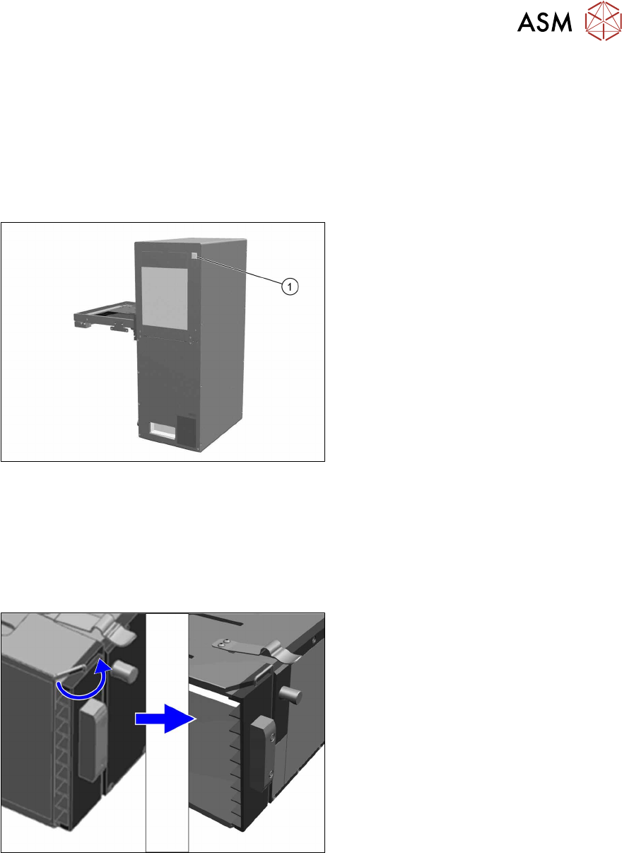
Fig.117: LED display
1. LED indicator
Green = Ready for operation
Red = Error
5.2 Task: Operating the feeder
5.2.1 Locking and unlocking the transportation lock
Unlock the transportation lock
Fig.118: Unlock the transportation lock
To unlock the transportation lock proceed as
follows:
► Slightly lift the hook and turn it side-
ways.
5 Tasks on the machine
5.2 Task: Operating the feeder
68 User Manual SIPLACE TX V1/V2 Series JEDEC Tray Feeder (JTF-ML2) 11/2019
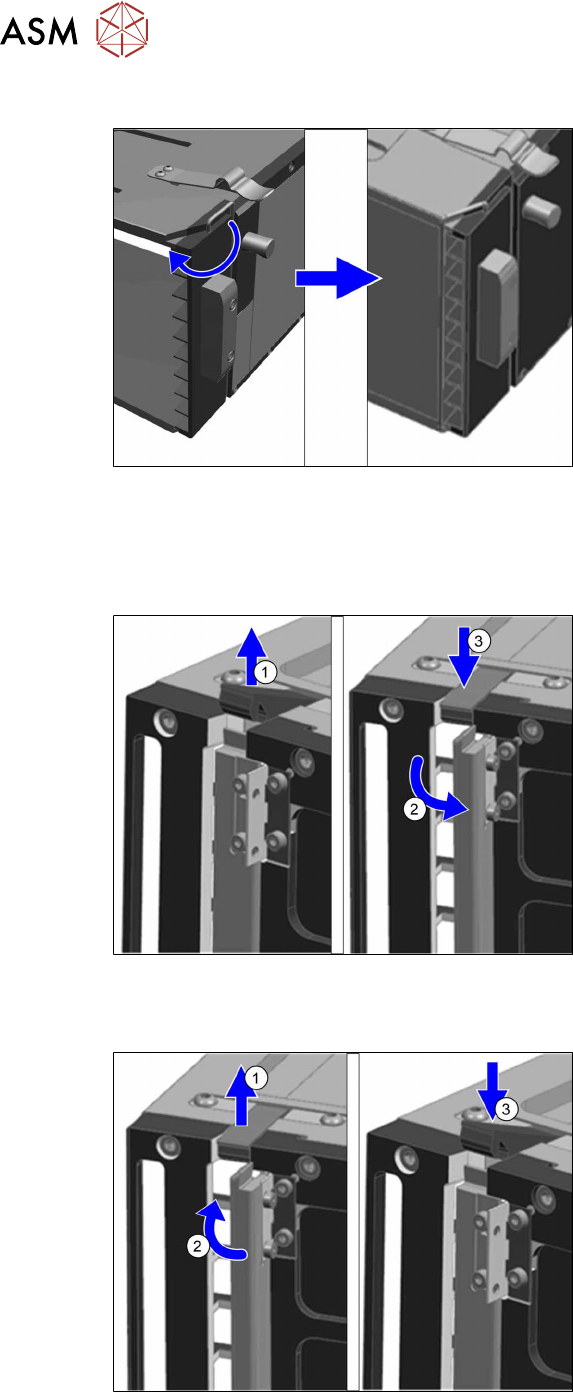
Lock the transportation lock
Fig.119: Lock the transportation lock
To lock the transportation lock proceed as
follows:
► Slightly lift the hook and turn it towards
the trays.
5.2.2 Locking and unlocking the direction lock
Unlocking the direction lock
Fig.120: Unlocking the direction lock
To unlock the direction lock proceed as fol-
lows:
► Unlock the lever(1).
► Move the direction lock outwards(2)
(position "open").
► Lock the lever(3).
Locking the direction lock
Fig.121: Lock the direction lock
To lock the direction lock proceed as fol-
lows:
► Unlock the lever(1).
► Move the direction lock inwards(2)
(position "close").
► Lock the lever(3).
5 Tasks on the machine
5.2 Task: Operating the feeder
User Manual SIPLACE TX V1/V2 Series JEDEC Tray Feeder (JTF-ML2) 11/2019 69
5.2.3 Pushing trays into and removing from the cassette
Pushing Trays into 9 Tray Cassettes
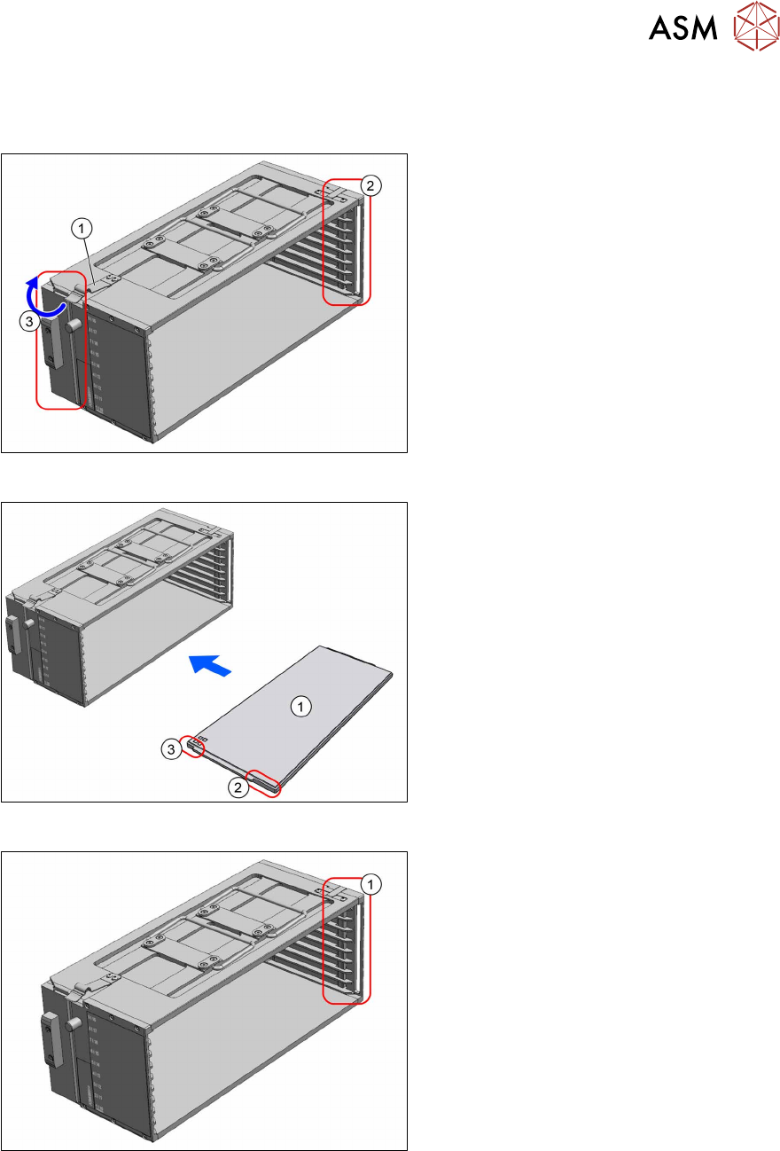
Fig.122: Transportation lock and direction lock
► Place the cassette down on a stabile
surface.
► Observe the orientation. The spring (1)
must point to the left.
► Ensure the direction lock(2) on the
right side is in position "open".
► Lock the transportation lock(3) on the
left side.
Fig.123: Loading 9 tray cassette
1. Tray
2. Long recess at the tray
3. Short recess at the tray
► Push the trays into the cassette. The
side with the short recess(3) is pushed
into the cassette first.
► Lock the direction lock(1) on the right
side.
► On the host system, link the components / tray code to the slot number of the cassette.