00198365-03_UM_JTF-ML2_TX12_V1-V2_EN.pdf - 第88页
7 Appendix 7.1 Excerpts from the Service Manual 88 User Manual SIPLACE TX V1/V2 Series JEDEC Tray Feeder (JTF-ML2) 11/2019 LED (test mode for reject box switched off – S2.1 ON) [03059783-04] LED Color Result State Signal…
7 Appendix
7.1 Excerpts from the Service Manual
User Manual SIPLACE TX V1/V2 Series JEDEC Tray Feeder (JTF-ML2) 11/2019 87
7.1.1.1 Board description Feeder Control Unit (FCU)
FCU 80 Mhz (V3)
●
X-FCU V3, X-Series [03170613‑xx]
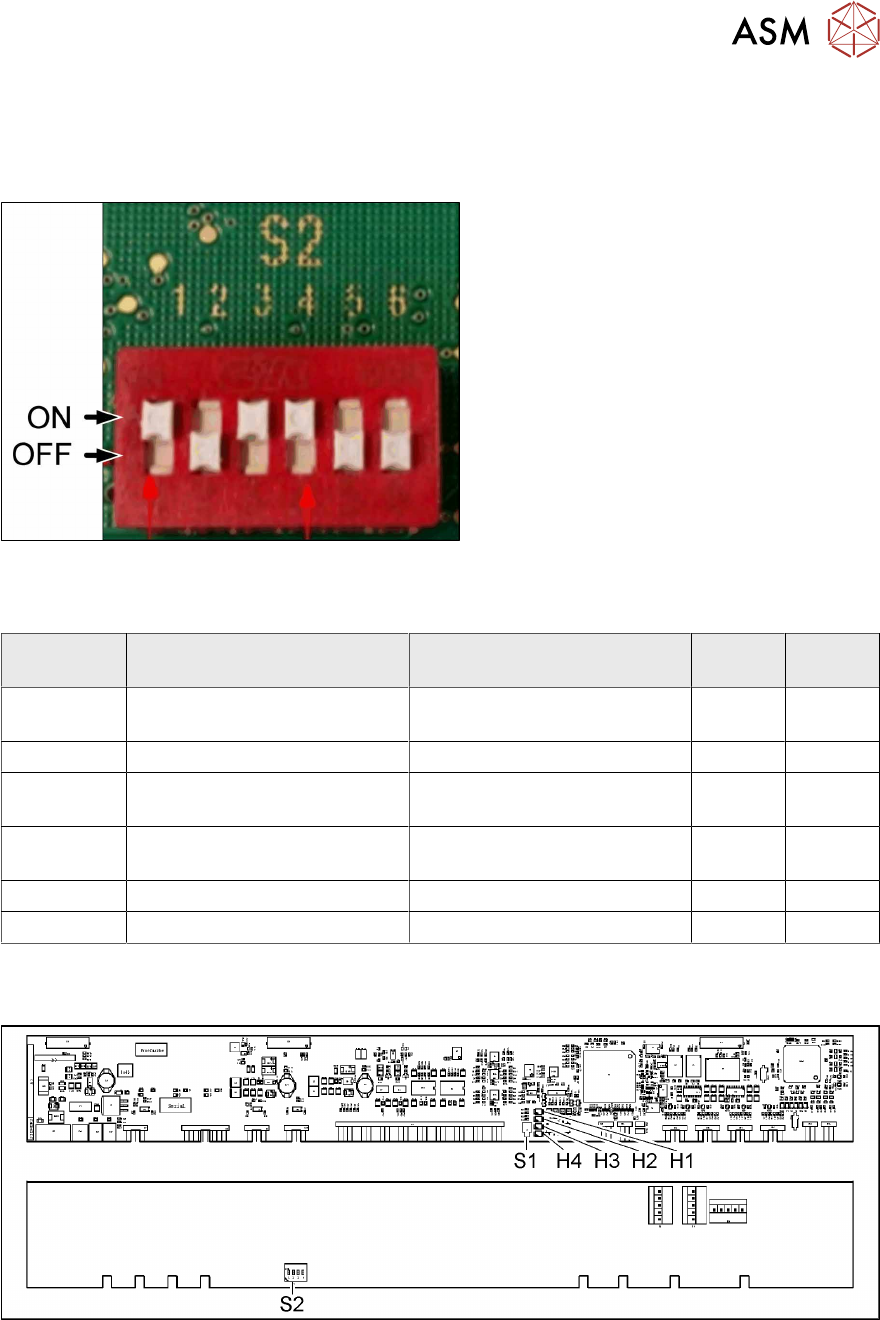
Fig.158: DIP switch S2 (example of FCU 40-fold shown)
► Set the DIP switch according to your
configuration.
DIP switch S2
S2 ON OFF 40 fold
FCU
60 fold
FCU
S2-SW1 Test mode for reject bins dis-
abled
Test mode for reject bins en-
abled
ON ON
S2-SW2 60 fold FCU 40 fold FCU OFF ON
S2-SW3 Without feed control
With virtual button
With feed control
Without virtual button
ON ON
S2-SW4 With tape cutter and NC func-
tion
Without tape cutter and NC
function
ON ON
S2-SW5 Not used Not used OFF ON
S2-SW6 Not used Not used OFF ON
FCU 40 Mhz
●
X-FCU V2, X series [03096377-xx]
Fig.159: FCU board
7 Appendix
7.1 Excerpts from the Service Manual
88 User Manual SIPLACE TX V1/V2 Series JEDEC Tray Feeder (JTF-ML2) 11/2019
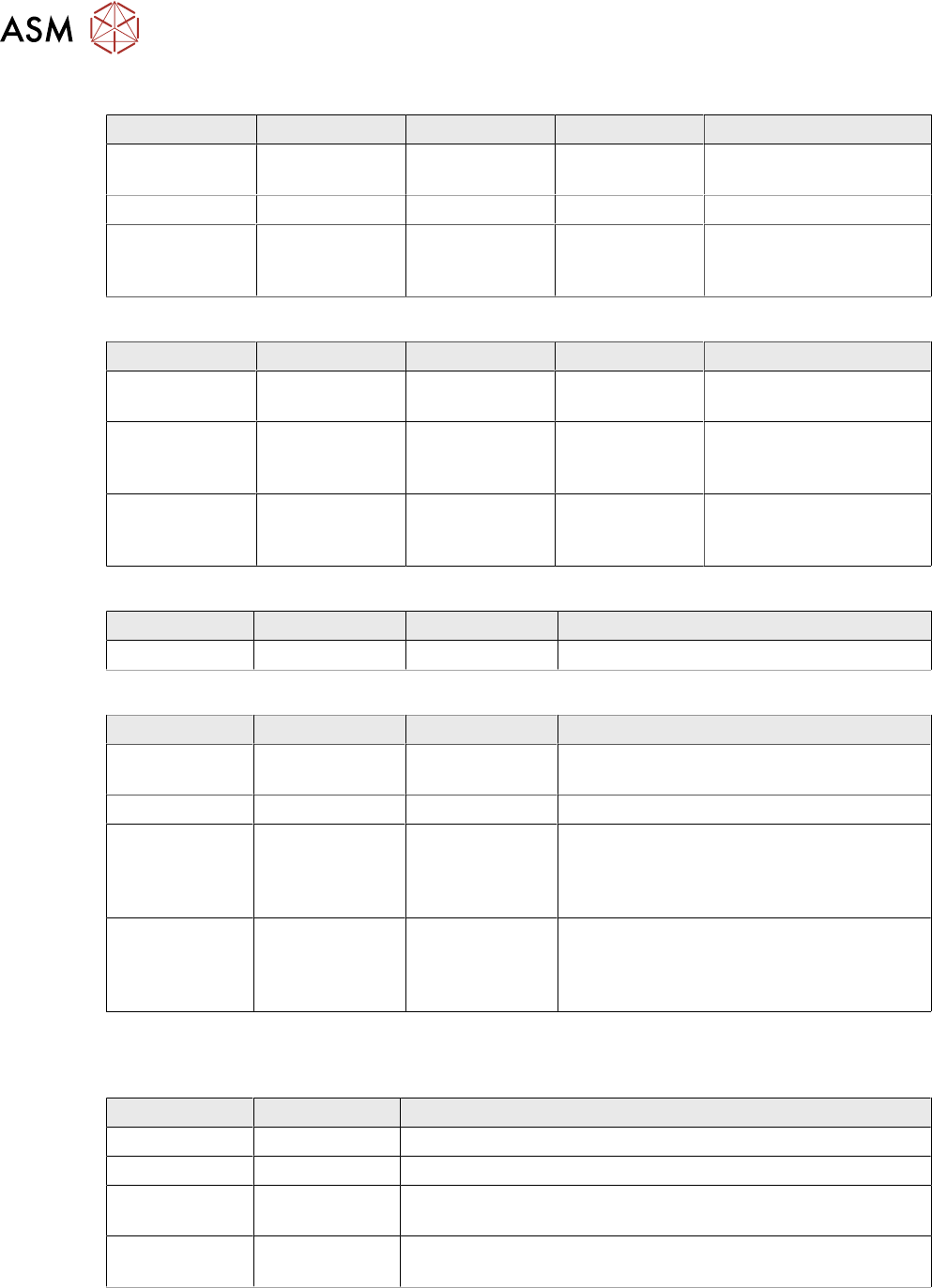
LED (test mode for reject box switched off – S2.1 ON) [03059783-04]
LED Color Result State Signal name Description
H1, H2, H3, H4 GN Sequential shift
light
LED1, 2, 3, 4 FCU OK
H1, H2, H3, H4 GN ON LED1, 2, 3, 4 eSW application missing
H1, H2, H3, H4 GN Flashing LED1, 2, 3, 4 FCU error, reboot place-
ment machine or replace
FCU
LED (test mode for reject box switched on – S2.1 OFF) [03059783-04]
LED Color Result State Signal name Description
H1 or H2 or H3
or H4
GN Flashes LED1 or 2 or 3
or 4
No sensor connected for
reject box 1 or 2 or 3 or 4
H1 or H2 or H3
or H4
GN OFF LED1 or 2 or 3
or 4
Sensor for reject boxes 1
or 2 or 3 or 4 connected
and no reject box inserted
H1 or H2 or H3
or H4
GN ON LED1 or 2 or 3
or 4
Sensor for reject boxes 1
or 2 or 3 or 4 connected
and no reject box inserted
Button S1 [03059783-04]
Button Result State Function Description
S1 OFF RESET When pressed
DIP switch S2 [03059783-04]
Switch Result State Signal name Description
S2.1 ON/OFF FCU_ENV3 ON: test mode for reject box switched off
OFF: test mode for reject box switched on
S2.2 OFF FCU_ENV2 40 fold FCU
S2.3 ON/OFF FCU_ENV1 ON: without insert control, with virtual but-
ton
OFF: with insert control, without virtual but-
ton
S2.4 ON/OFF FCU_ENV0 ON: with tape cutter and with nozzle
changer functionality
OFF: without tape cutter and without nozzle
changer functionality
If an "X-FCU / X-Series" [03059623-xx] is fitted as replacement for an "FCU X-Series" [03020068-
xx] in the "COT insert X-Series" or at the "Docking station for component trolley SIPLACE X", you
need to set the DIP switch as follows:
Switch Result State Comment
S2.1 ON Test mode for reject bin switched off
S2.2 OFF FCU for 40 feed tracks
S2.3 OFF COT insert control with pushbutton / without button GUI (vir-
tual).
S2.4 OFF "HW version 6" meaning without tape cutter and nozzle
changer functionality
7 Appendix
7.1 Excerpts from the Service Manual
User Manual SIPLACE TX V1/V2 Series JEDEC Tray Feeder (JTF-ML2) 11/2019 89
7.1.2 Nozzle Changer Setting
7.1.2.1 Setting the nozzle changer height
Parts, equipment and tools
●
Measuring scale
●
NC shim plate (0.3mm) [03021079-xx]
Overview
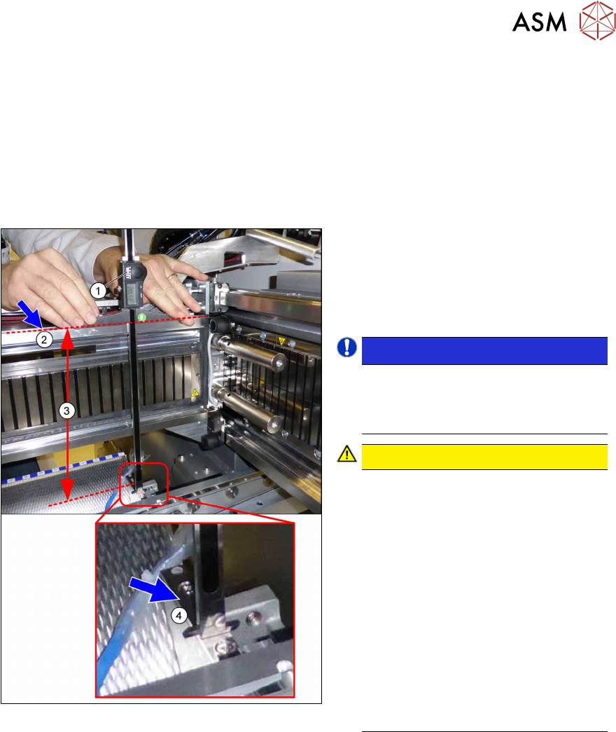
Fig.160: Overview of measurement procedure
1. Measuring scale
2. Top edge of the X axis upper linear
guide
3. Values to be set (277 +/- 0.2 mm)
4. Nozzle changer contact surface
NOTICE!
Alternatively, you can measure from
the top edge of the lower guide rail of
the gantry. In this case the distance is
116.0+/‑0.2mm.
.
CAUTION!
Only with mixed mode option
If applicable, observe the deviating
measurements for the mixed mode
option:
Installation height of NC:
280.65 +/ 0.2 mm
Measured from the upper edge of the
top linear guide
OR
119.65 +/ 0.2 mm
Measured from the upper edge of the
bottom linear guide
See also the assembly instruction
manual "Option Mixed Mode –
SIPLACE TX2i" [00198536‑xx]
.