00198365-03_UM_JTF-ML2_TX12_V1-V2_EN.pdf - 第50页
4 Setting up and commissioning 4.2 Retrofitting in the SIPLACE TX-Series 50 User Manual SIPLACE TX V1/V2 Series JEDEC Tray Feeder (JTF-ML2) 11/2019 Fig.86: Mounting the conveyor 6 ► Push the plate (1) until end positio…
4 Setting up and commissioning
4.2 Retrofitting in the SIPLACE TX-Series
User Manual SIPLACE TX V1/V2 Series JEDEC Tray Feeder (JTF-ML2) 11/2019 49
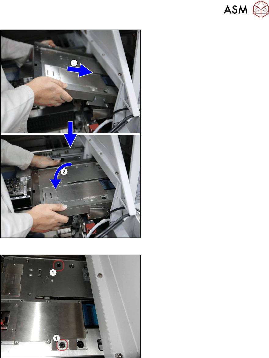
Fig.84: Mounting the conveyor 4
► Before mounting the conveyor, loosely
insert the cables [03134469‑xx] and
[03134468‑xx] into the mounting bracket
(see also next figure).
► (1) Insert the conveyor. Make sure that
it fits correctly into the conveyor pivot.
► (2) Swing the conveyor down onto the
SIPLACE JTF-ML2 adapter.
Fig.85: Mounting the conveyor 5
► Fasten the conveyor with two
screws(1) (ISO7379 - 8x16-12.9) on
the SIPLACE JTF-ML2 adapter.
4 Setting up and commissioning
4.2 Retrofitting in the SIPLACE TX-Series
50 User Manual SIPLACE TX V1/V2 Series JEDEC Tray Feeder (JTF-ML2) 11/2019
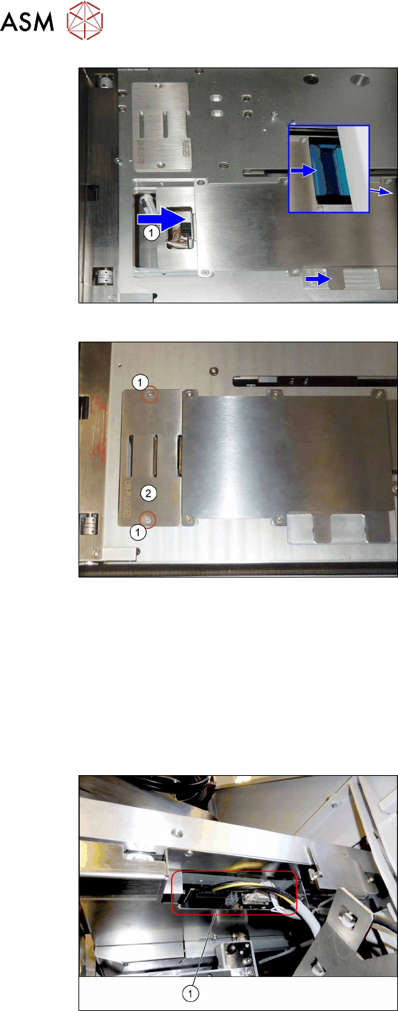
Fig.86: Mounting the conveyor 6
► Push the plate(1) until end position to
the right.
This way the electric connection
between conveyor and tower is
established (see blue window).
If necessary, hold against the plug on
the tower side for better connection.
Fig.87: Mounting the conveyor 7
► Fit the cover(2) using two screws(1).
4.2.5.9 Establishing the electrical connections on the SIPLACE TX-Series V1
On the SIPLACE TX V1, use the following cables for this:
●
Cable COTi TX: DC control to SIPLACE JTF-ML [03134469‑xx]
●
Cable COTi TX: CAN bus3 to SIPLACE JTF-ML [03134468‑xx]
Also observe the detailed circuit diagrams (see below).
► Remove the cover above the FCU connectors (see also 7.1.1 "Replacing the Feeder Control
Unit (FCU)" [}85]).
Fig.88: Connector on the SIPLACE JTF-ML2
► (1) Plug in the cables [03134469‑xx]
and [03134468‑xx] at the SIPLACE
JTF‑ML2.
4 Setting up and commissioning
4.2 Retrofitting in the SIPLACE TX-Series
User Manual SIPLACE TX V1/V2 Series JEDEC Tray Feeder (JTF-ML2) 11/2019 51
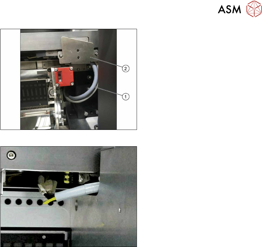
Fig.89: Cable routing
► Pay attention to the correct running of
the cables [03134469‑xx] and
[03134468‑xx](1) at the conveyor. The
cables have to be in the mounting
bracket(2).
Fig.90: Cable with docked COT
► Make sure there is a gap between the
cable and the COT to avoid cable rub-
bing during insertion or removal of
COT.
► Run the cables below the conveyor of the SIPLACE JTF‑ML2 towards the back of the COT insert.
► Connect the CAN bus cable [03134468‑xx] to connector X17 at the FCU.
► Locate the connectors X1.JTF and X4.COTi1 in the machine base.
► Connect the power cable [03134469‑xx] to connectors X1.JTF and X4.COTi1 at the cable har-
ness. If necessary also use adapter cable [03160347‑xx].