00198365-03_UM_JTF-ML2_TX12_V1-V2_EN.pdf - 第69页
5 Tasks on the machine 5.2 Task: Operating the feeder User Manual SIPLACE TX V1/V2 Series JEDEC Tray Feeder (JTF-ML2) 11/2019 69 5.2.3 Pushing trays into and removing from the cassette Pushing Trays into 9 Tray Cassettes…
5 Tasks on the machine
5.2 Task: Operating the feeder
68 User Manual SIPLACE TX V1/V2 Series JEDEC Tray Feeder (JTF-ML2) 11/2019
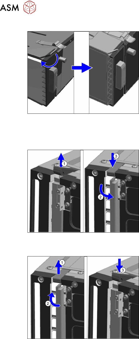
Lock the transportation lock
Fig.119: Lock the transportation lock
To lock the transportation lock proceed as
follows:
► Slightly lift the hook and turn it towards
the trays.
5.2.2 Locking and unlocking the direction lock
Unlocking the direction lock
Fig.120: Unlocking the direction lock
To unlock the direction lock proceed as fol-
lows:
► Unlock the lever(1).
► Move the direction lock outwards(2)
(position "open").
► Lock the lever(3).
Locking the direction lock
Fig.121: Lock the direction lock
To lock the direction lock proceed as fol-
lows:
► Unlock the lever(1).
► Move the direction lock inwards(2)
(position "close").
► Lock the lever(3).
5 Tasks on the machine
5.2 Task: Operating the feeder
User Manual SIPLACE TX V1/V2 Series JEDEC Tray Feeder (JTF-ML2) 11/2019 69
5.2.3 Pushing trays into and removing from the cassette
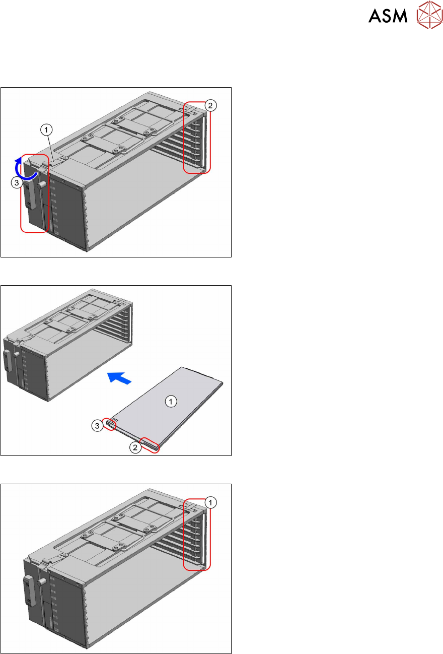
Pushing Trays into 9 Tray Cassettes
Fig.122: Transportation lock and direction lock
► Place the cassette down on a stabile
surface.
► Observe the orientation. The spring (1)
must point to the left.
► Ensure the direction lock(2) on the
right side is in position "open".
► Lock the transportation lock(3) on the
left side.
Fig.123: Loading 9 tray cassette
1. Tray
2. Long recess at the tray
3. Short recess at the tray
► Push the trays into the cassette. The
side with the short recess(3) is pushed
into the cassette first.
► Lock the direction lock(1) on the right
side.
► On the host system, link the components / tray code to the slot number of the cassette.
5 Tasks on the machine
5.2 Task: Operating the feeder
70 User Manual SIPLACE TX V1/V2 Series JEDEC Tray Feeder (JTF-ML2) 11/2019
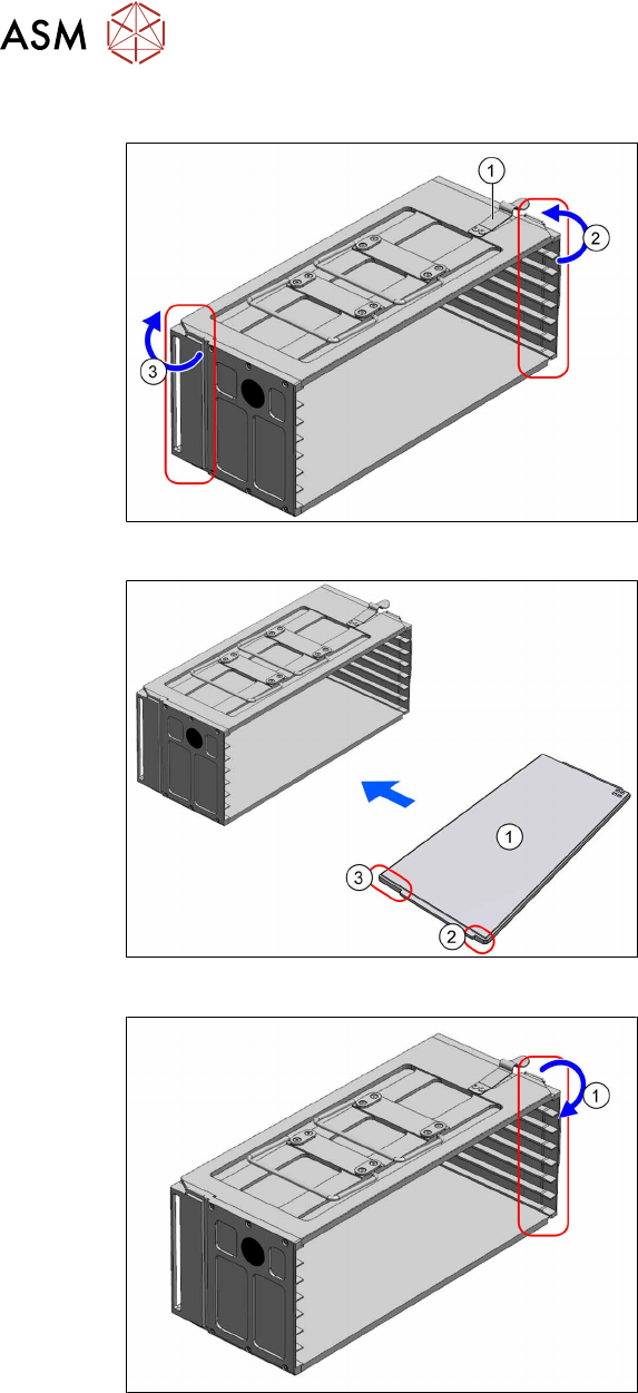
Pushing Trays into 7 Tray Cassettes
Fig.124: Transportation locks
► Place the cassette down on a stabile
surface.
► Observe the orientation. The spring (1)
must point to the right.
► Unlock the transportation lock(2) on
the right side.
► Lock the transportation lock(3) on the
left side.
Fig.125: Loading 7 tray cassette
1. Tray
2. Short recess at the tray
3. Long recess at the tray
► Push the trays into the cassette. The
side with the long recess(3) is pushed
into the cassette first.
Fig.126: Transportation lock
► Lock the transportation lock(1) on the
right side.
► On the host system, link the components / tray code to the slot number of the cassette.
Removing the trays from the cassette
► Place the cassette down on a stabile surface.
► Unlock the transportation lock (cassette with 7 trays) or the direction lock (cassette with 9 trays).
► Pull the trays out of the slots.