00193790-01.pdf - 第110页
2 English Installat ion and Getting Started with CACCIA 2.10 Overview of the J umper Settings for Individual Subsyst ems Issue 07/2004 44 2.10.2.2 Vision Board (analog) The vision b oard is conn ected on the top of the h…
Installation and Getting Started with CACCIA 2 English
Issue 07/2004 2.10 Overview of the Jumper Settings for Individual Subsystems
43
Description
LED‘S and DIP switches on the head interface:
LED 1-7 (functional check)
– SPI - Serial parallel interface (A/D or D/A converter in future)
– D-ON - Digital ON 5V DC/DC Converter
– H-OK - Head adapter board connected
– C-In - CAN Internal not used
– MRST - Main Reset
–F-UC- notused
– MP - Main Power fail, mean 5 V power supply being missing at the machine
(e.g. CAN Bus)
LED 1-10 (LED´s for voltages)
– Vcc - Power supply +5 V head interface
– N15V - Minus 15 Volt (from the Axis unit → Error → LED red)
– P3,3V - Not used
– P15V - Plus 15 Volt (from the Axis unit → Error → LED red)
– P24V - 24 Volt power supply (e.g. stepper motor)
–AVER-Notused
– ENAN- Notused
– P5V - 5 Volt Power supply track signals X-Axis → ON Power fail
– VccF - 5 Volt for digital
– TMP - Temperature monitoring X-Axis
2 English Installation and Getting StartedwithCACCIA
2.10 Overview of the Jumper Settings for Individual Subsystems Issue 07/2004
44
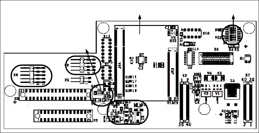
2.10.2.2 Vision Board (analog)
The vision board is connected on the top of the head interface. That board is used on the gantry
with a C&P head and Twin head.
Fig. 2 - 34 Vision board
Legend
(1) Connector illumination PCB camera
(2) Connector PCB camera
(3) LED‘s P15V - 15Volt / Vcc - Power supply vision board
(4) DIP Switch
(5) CAN Processor 16 Bit (additional board on the vision board)
(6) DC/DC Converter 15 → 5V for visionsystem.
4
5
1
3
2
6
Installation and Getting Started with CACCIA 2 English
Issue 07/2004 2.10 Overview of the Jumper Settings for Individual Subsystems
45
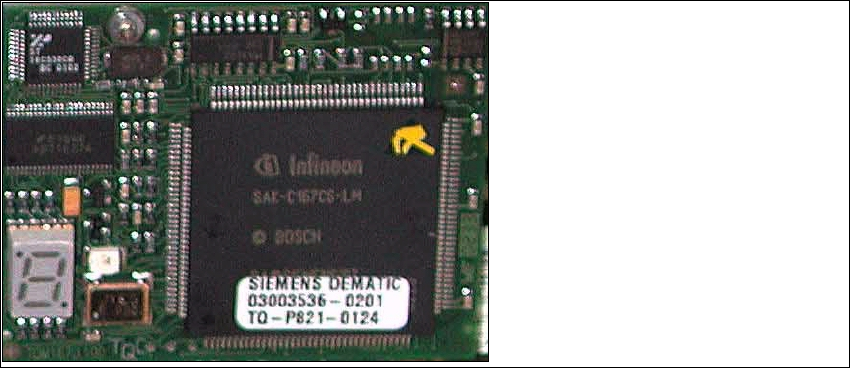
2.10.2.3 CAN Processor Board 16 Bit
The 16 BIT CAN Processor is used for different functions of the following units:
– Vision board, communication and control via the ICOS system.
– Main board Twin head, control the vacuum generator.
– Vision board for the stationary IC (FC) - Camera, communication and control via the ICOS
system in sector 2 and 4.
Fig. 2 - 35 16 Bit Processor
Description 7 Segment display (Standard mode "." flashed):
– After switch ON the machine appears "0" on the display
– Display "b" Bios is started.
– Display flash alternately "b" and "." → none Application available or can not started.
– Display "-I" und "I-" Application is loaded and now starts.
– The "." on the display flashed.
(1) 7 Segment display
(2) LED red at the manual RESET on
the Processors
(3) 16 Bit Processor
2
3
1