00193790-01.pdf - 第112页
2 English Installat ion and Getting Started with CACCIA 2.10 Overview of the J umper Settings for Individual Subsyst ems Issue 07/2004 46 2.10.2.4 Head Adapter for 6/12 C&P Head At the head modularity we can use the …
Installation and Getting Started with CACCIA 2 English
Issue 07/2004 2.10 Overview of the Jumper Settings for Individual Subsystems
45
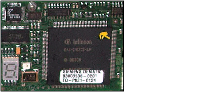
2.10.2.3 CAN Processor Board 16 Bit
The 16 BIT CAN Processor is used for different functions of the following units:
– Vision board, communication and control via the ICOS system.
– Main board Twin head, control the vacuum generator.
– Vision board for the stationary IC (FC) - Camera, communication and control via the ICOS
system in sector 2 and 4.
Fig. 2 - 35 16 Bit Processor
Description 7 Segment display (Standard mode "." flashed):
– After switch ON the machine appears "0" on the display
– Display "b" Bios is started.
– Display flash alternately "b" and "." → none Application available or can not started.
– Display "-I" und "I-" Application is loaded and now starts.
– The "." on the display flashed.
(1) 7 Segment display
(2) LED red at the manual RESET on
the Processors
(3) 16 Bit Processor
2
3
1
2 English Installation and Getting StartedwithCACCIA
2.10 Overview of the Jumper Settings for Individual Subsystems Issue 07/2004
46
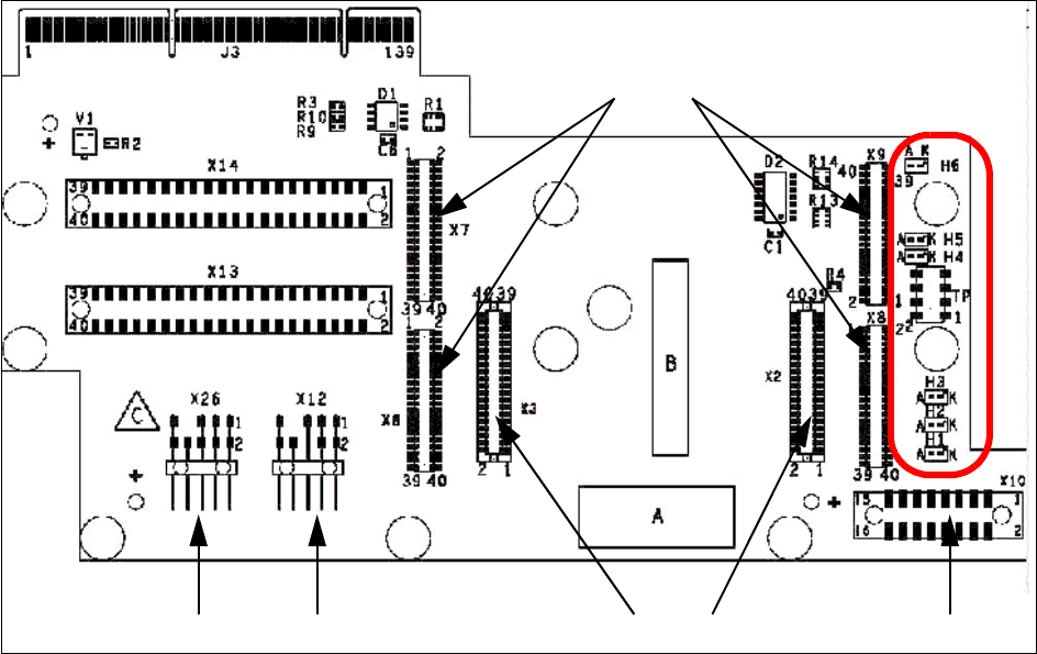
2.10.2.4 Head Adapter for 6/12 C&P Head
At the head modularity we can use the same head adapter for the 6 and 12 segment C&P heads.
The head adapter must be exchanged if you mounting the Twin head.
Fig. 2 - 36 Head adapter for 6/12 C&P head
Legend
(1) X6-X9 Connector for CAN Processor board’ 80C515C 8Bit
(2) X2/X3 Connector for the stepping motor board
(3) X10 Connector vacuum board
(4) X12 Dp station (motor, track signal)
(5) X26 Option component sensor
(6) X13/14 connector for the flat cable to the intermediate distribution board
(7) Connector to the head interface
1
2
45
3
6
7
LED‘S
Installation and Getting Started with CACCIA 2 English
Issue 07/2004 2.10 Overview of the Jumper Settings for Individual Subsystems
47
Description LED‘s:
–LZOS Light barrier Z-axis upper stop
–LZUS Light barrier Z-axis down position
– LSM Stepper motor board not connected
–LSZD Light barrier Swivel in and turning dp-station
–LSVZ Light barrier Vacuum / air kiss Z-axis
– LSVA Light barrier Vacuum / air kiss reject position
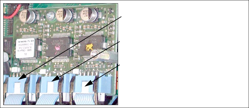
2.10.2.5 Stepping motor board
The stepping motor board for the valve drivers and the swivel function on the DP station are
mounted onto the head adapter below the CAN processor board 80C515C. Is the board missing
the LSM LED at the head adapter is ON. In this case the CAN Bus Processor board can not fixed.
Fig. 2 - 37 Stepping motor board
2
3
1
Stepping motor reject position
(for S/F. HS and HF machine)
Steppingmotorpickup,placement and
reject position HF/HF3
Stepping motor DP-axis