00193790-01.pdf - 第74页
2 English Installat ion and Getting Started with CACCIA 2.1 General Issue 07/2004 8 2.1.2.5 Overvie w of the CAN Bus S tructure i n SIPLACE S-27 HM Machines Fig. 2 - 5 Overview of the CAN Bus S tructure in SIPLACE S-27 H…
Installation and Getting Started with CACCIA 2 English
Issue 07/2004 2.1 General
7
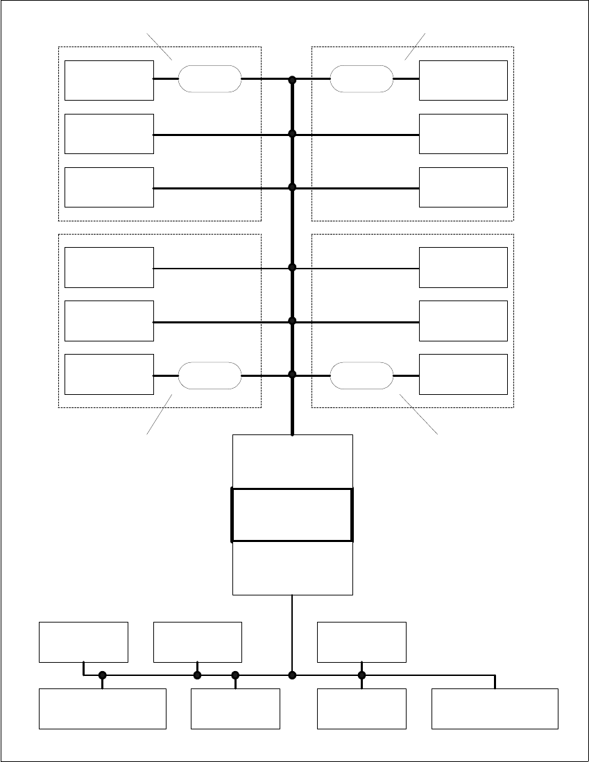
2.1.2.4 Overview of the CAN Bus Structure in SIPLACE HS-50 Machines
Fig. 2 - 4 Overview of the CAN Bus Structure in SIPLACE HS-50 Machines
Component
Table 4
Tape Cutter 4
Head Gantry 4
Head Gantry 3
Tape Cutter 3
Component
Table 3
Machine
Controller
CAN assembly 2
125 kbps CAN bus
CAN assembly 1
500 kbps CAN bus
Decoupling
Unit
Decoupling
Unit
Component
Table 2
Tape Cutter 2
Head Gantry 2
Decoupling
Unit
Decoupling
Unit
Head Gantry 1
Tape Cutter 1
Component
Table 1
SLIO 1 SLIO 2
SLIO 3
( optional)
Conveyor Controller 1
SLIO
Conveyor 1
SLIO
Conveyor 2
Conveyor Controller 2
Sector 1
Sector 3
Sector 4
Sector 2
2 English Installation and Getting StartedwithCACCIA
2.1 General Issue 07/2004
8
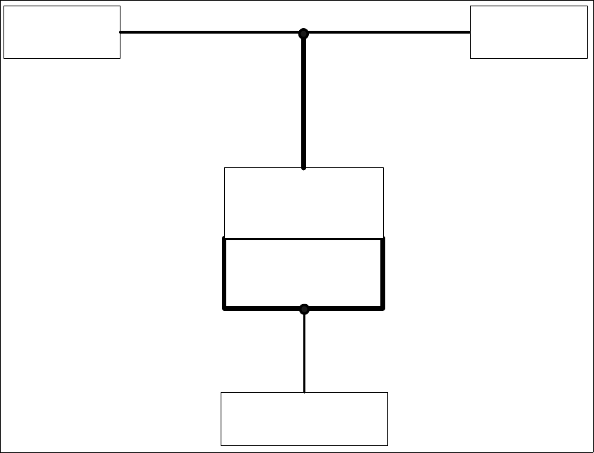
2.1.2.5 Overview of the CAN Bus Structure in SIPLACE S-27 HM Machines
Fig. 2 - 5 Overview of the CAN Bus Structure in SIPLACE S-27 HM Machines
Head Gantry 2
Machine
Controller
CAN Assembly 1
1MbpsCANBus
Head Gantry 1
Conveyor Controller 1
Installation and Getting Started with CACCIA 2 English
Issue 07/2004 2.1 General
9
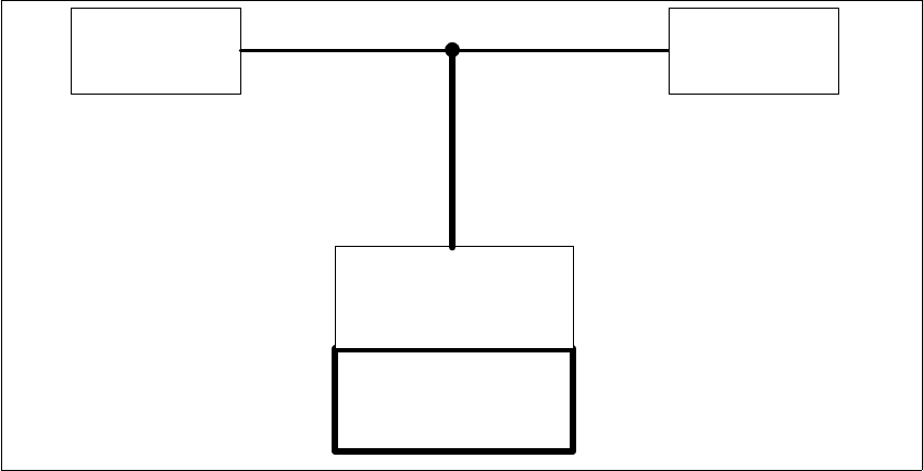
2.1.2.6 Overview of the CAN Bus Structure in F5 HM Machines
Fig. 2 - 6 Overview of the CAN bus structure in F5 HM machines
Machine
Controller
CAN Assembly 1
1 Mbps CAN Bus
Head Gantry
Lightning
Control
IC Camera