00196478-08_MM_SX12DX12_en.pdf - 第15页
Introduction 1.3.2 Calculation of Maintenance Intervals Maintenance Notes Maintenance Manual SIPLACE SX1/SX2/DX1/DX2 15 1.3.2 1 . 3 . 2 C a lc u la t io n o f M a in t e n a n c e I n t e r v a ls Calculation of Maintena…
Introduction
Maintenance Notes 1.3.1 Minor and Major Maintenance
14 Maintenance Manual SIPLACE SX1/SX2/DX1/DX2
1.3
1.3 Maintenance Notes
Maintenance Notes
See also
1.1.7 Safety Instructions for Maintenance Tasks [ ➙ 9]
1.3.1
1.3.1 Minor and Major Maintenance
Minor and Major Maintenance
Maintenance to production equipment is subject to underlying conditions stipulated by the production
schedule and other organizational circumstances. The availability of the staff trained and authorized to
perform SIPLACE maintenance also plays a role in the ability to realize maintenance work.
To facilitate easier realization of SIPLACE maintenance in the daily work routine, this SIPLACE mainte-
nance manual takes into account the degree of complexity for each maintenance task. The tasks are
therefore differentiated between Minor Maintenance and Major Maintenance.
Minor Maintenance
Minor Maintenance includes weekly maintenance tasks. The tasks of the weekly maintenance intervals
can be carried out using the Maintenance Manual; thus no special training is needed. These tasks are
typically executed by the operating personnel.
Minor Maintenance summarizes all maintenance tasks that are to be carried out on a weekly basis. The
average time needed is approximately 1 hour per line, depending on the line configuration as well as the
number of persons who carry out the maintenance and their experience.
Minor Maintenance = weekly maintenance break, simple tasks
Major Maintenance
Major Maintenance summarizes recommended maintenance tasks with a higher degree of complexity
that are usually carried out every 6 or 12 months. These tasks require a special training.
Normally, these tasks are carried out by adequately trained operating, maintenance or service person-
nel. Major Maintenance tasks are planned and carried out on a 6 and 12 month basis (3 month basis for
C&P20). Planning the Major Maintenance is normally connected to the planned major maintenance of
the oven within the production line.
Major Maintenance = 3, 6, 12 monthly maintenance breaks, complex tasks
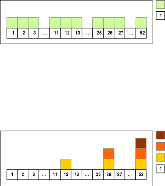
Weekly maintenance tasks
Week
12 monthly maintenance work
6 monthly maintenance work
3 monthly maintenance work
Week
Introduction
1.3.2 Calculation of Maintenance Intervals Maintenance Notes
Maintenance Manual SIPLACE SX1/SX2/DX1/DX2 15
1.3.2
1.3.2 Calculation of Maintenance Intervals
Calculation of Maintenance Intervals
The SIPLACE maintenance intervals are time-based and set according to the following conditions:
▪ Shift model: eight hours per shift, three shifts per day, five days a week and fifty weeks a year.
▪ Real placement performance in accordance with machine specifications
▪ Environmental and production conditions: see document "Main Power and Compressed Air Config-
uration"
1.3.2.1
1.3.2.1 Adjusting the Maintenance Intervals to Actual Production Conditions
Adjusting the Maintenance Intervals to Actual Production Conditions
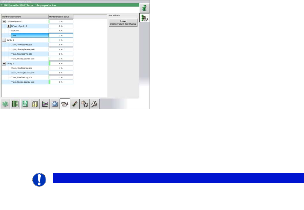
The maintenance status is calculated from the placement cycles, temperature and operating hours. The
status is shown as a progress bar (0 – 100 %).
Placement cycles for maintenance intervals:
▪ CPP: 40 mill. placed components
▪ C&P20: 30 mill. placed components
▪ C&P20A/M/P: 37.5 mill. placed components
Some customers want to adjust maintenance intervals to
their actual environment and production conditions. A
maintenance monitor can also be accessed in the station
software for some assemblies (from SW703.02).
The maintenance monitor is available for the following as-
semblies:
▪CPP
▪ C&P20/A/M/P
▪ X and Y axis (SX1/SX2/DX1/DX2 only)
NOTICE
Maintenance counter
► After maintenance has been completed, the maintenance counter needs to be reset for the
assembly concerned.
Introduction
Other Instructions 1.4.1 Environmentally-Friendly Disposal of Materials and Components
16 Maintenance Manual SIPLACE SX1/SX2/DX1/DX2
1.4
1.4 Other Instructions
Other Instructions
1.4.1
1.4.1 Environmentally-Friendly Disposal of Materials and Components
Environmentally-Friendly Disposal of Materials and Components
SIPLACE products are manufactured using only materials and parts that can be easily separated and
disposed of in an environmentally-friendly way.
1.4.2
1.4.2 Use of Original SIPLACE Accessories and Spare Parts
Use of Original SIPLACE Accessories and Spare Parts
Only use original spare parts and authorized accessories. The use of other parts will affect safety and
will invalidate the liability for any consequential damage.
1.4.3
1.4.3 ESD Guidelines
ESD Guidelines
1.4.3.1
1.4.3.1 Definition of ESD
Definition of ESD
1.4.3.2
1.4.3.2 Important Measures to Protect Against Static Charging
Important Measures to Protect Against Static Charging
► Most plastics can easily become charged and must therefore be kept away from at-risk components.
► Always ensure that people, the workplace and packaging are safely earthed when handling electro-
static sensitive components.
1.4.3.3
1.4.3.3 Handling ESD Modules
Handling ESD Modules
Do not touch electronic modules unless it is absolutely essential to do so in order to carry out other work.
If it is necessary, make sure that you do not touch the pins or printed conductors when you pick up flat
modules.
Do not touch components unless
▪ You are constantly earthed by an ESD wrist strap or
▪ You are wearing ESD shoes or ESD shoe earthing strips on an ESD floor.
Always discharge yourself before you touch an electronic module. To do this, simply touch a conductive
and earthed object immediately before you touch the module (such as unpainted parts of a switch cab-
inet, a water pipe, etc.).
Do not allow modules with chargeable and highly insulating materials to touch one another, e.g. plastic
films, insulating table surfaces or items of clothing made from synthetic fibers.
NOTICE
Observe the applicable regulations
The company operating the system has sole responsibility for the proper, environmentally-
friendly disposal of machines, working materials, consumables and wear parts.
► Please observe your national statutory provisions for waste disposal and environmental
protection.
Almost all of the modules in use today are equipped with highly integrated MOS blocks and compo-
nents. The manufacturing techniques used mean that these electronic components are extremely sen-
sitive to overvoltage and thus to electrostatic discharge.
The abbreviation for such modules is 'ESD' (Electrostatic Sensitive Device). This is
used internationally, although the German abbreviation 'EGB' may also be seen. The
following symbol on cabinet rating plates, racks or packaging indicates that compo-
nents which are sensitive to electrostatic discharge have been used and thus that the
modules concerned are also touch-sensitive.
ESDs can be destroyed by voltages and power levels that are far below the level that can be perceived
by humans. Such voltages occur if a person touches a component or module without earthing them-
selves. Components that are exposed to such overvoltages do not generally appear to be defective im-
mediately - incorrect behavior starts after the component or module has been in operation for some
time.