00196478-08_MM_SX12DX12_en.pdf - 第43页
Major Maintenance 5.2.1 Tools, Consumables, Spare and Wear Parts Maintenance Tasks for Base Machine Maintenance Manual SIPLACE SX1/SX2/DX1/DX2 43 5.2 5 . 2 M a in t e n a n c e T a s k s f o r B a s e M a c h in e Mainte…

Major Maintenance
Maintenance Intervals for Major Maintenance
42 Maintenance Manual SIPLACE SX1/SX2/DX1/DX2
2305 - Major - Gantry - SXDX12 V1 V2
2405 - Major - Conveyor - SXDX12 V1
3005 - Major - Nozzles/Nozzle Magazines
7005 - Major - Vacuum Pump - SX12V2 SXDX4 X34iS
9000 – Foot not e * Maintenanc e display
* see also maintenance display
9000 – Foot note ** 3 shift operation
** This value is for 3 shift operation (7500 hours of operation). Longer intervals can be planned for other
operation setups. Observe the manufacturer's maintenance manual.
See also
1.3.2 Calculation of Maintenance Intervals [ ➙ 15]
Maintenance tasks
Gantry
Duration
[min]
Each
week
Every 3
months
Every 6
months
Every 12
months
Grease and clean the X axis guide bearing 2 X*
Cleaning the Linear Guides of the X Axis 2 X
Grease and clean the Y axis guide bearing 2 X*
Cleaning the Linear Guides of the Y Axis 2 X
Cleaning the X Axis Scale 2 X
Cleaning the Y Axis Scale 2 X
Replace the loose bearing lubrication system X
axis (if present)
2X
Replace the loose bearing lubrication system Y
axis
2X*
Maintenance tasks
Conveyor
Duration
[min]
Each
week
Every 3
months
Every 6
months
Every 12
months
Adjusting the Conveyor Sides for DC 2 X
Cleaning and Preserving the Conveyor
▪ Hexagonal shafts
▪ Linear guide rails
▪ Ball screws
▪ Guide shaft
▪ Clamping surfaces (DT only)
11 X
Maintenance tasks
Nozzle magazines
Duration
[min]
Each
week
Every 3
months
Every 6
months
Every 12
months
Cleaning the Twin Nozzle Magazines 3 X
Maintenance tasks
Vacuum pump
Duration
[min]
Each
week
Every 3
months
Every 6
months
Every 12
months
Checking/Replacing the Filter Insert 15 X**
Major Maintenance
5.2.1 Tools, Consumables, Spare and Wear Parts Maintenance Tasks for Base Machine
Maintenance Manual SIPLACE SX1/SX2/DX1/DX2 43
5.2
5.2 Maintenance Tasks for Base Machine
Maintenance Tasks for Base Machine
5.2.1
5.2.1 Tools, Consumables, Spare and Wear Parts
Tools, Consumables, Spare and Wear Parts
▪ ESD wristband [00320279-xx]
▪ Lint-free cloths [03082092-xx]
▪ Set of Allen keys
▪ A weak or slightly alkaline cleaning agent
▪ Filter element 40 µm [03003717-xx]
▪ Filter element 5 μm [03050213-xx]
▪ O-ring 8.5x1.6 [03078577-xx] (for guide roller on protective covers)
▪ Gas pressure spring D3D3B90-135-430-004/230N [03086743-xx], if required
▪ Buffer cover-guide [03075364-xx], if required
▪ Pulley, complete (for flap covers) [03078561-xx], if required
▪ Service manual for your machine
5.2.2
5.2.2 Performing Maintenance Tasks
Performing Maintenance Tasks
5.2.2.1
5.2.2.1 Checking the Safety Features
Checking the Safety Features
Danger - No t functioning safety feature s
► Make sure that the placement system is switched on and the operating system has started up.
► Make sure that "Control on" is set on the placement machine. You can tell this from the main fault
indicator.
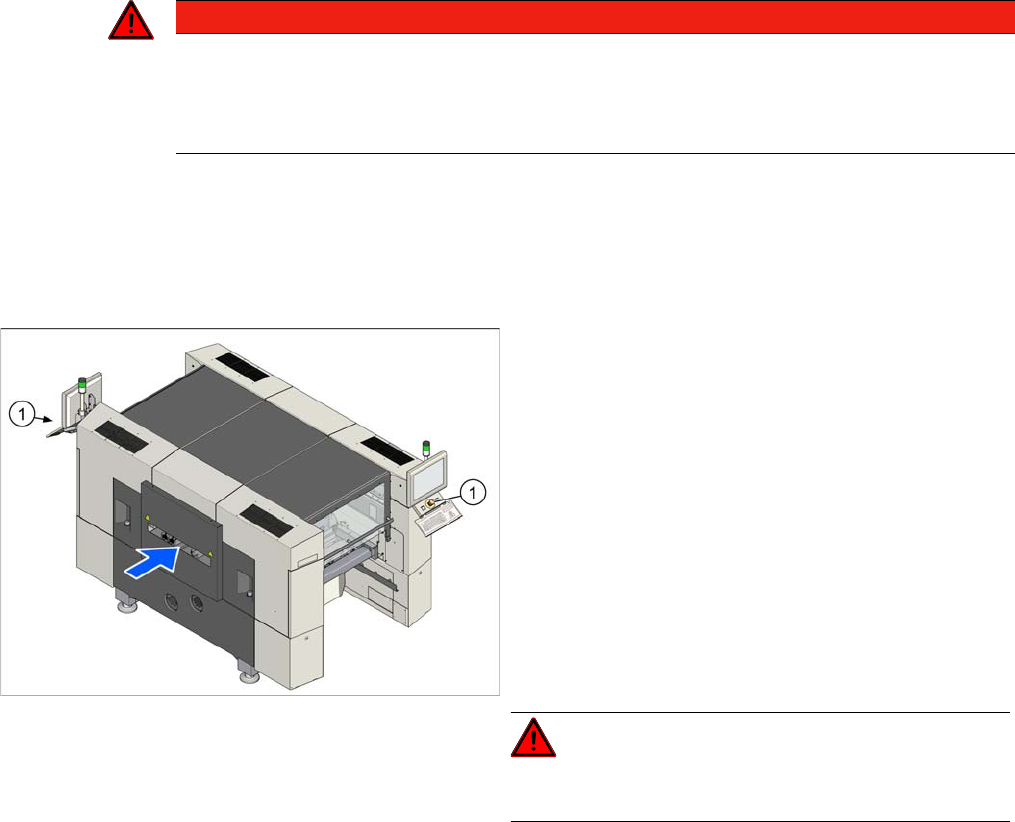
EMERGENCY STOP button
DANGER
Not functioning safety features
Not functioning safety features are dangerous.
► If any of the safety features does not function, switch off the machine immediately and se-
cure the machine against unauthorized reactivation.
► Check the EMERGENCY STOP buttons (1) for dam-
age.
► Press the Start button.
► Check if all actuated emergency stop buttons are
shown at the station software.
Check if the control system switches off immediately
when you actuate the button. A message must be dis-
played on the user interface and you should hear
compressed air blowing off.
If this is not the case, have the security circuit
checked and any damaged components replaced by
authorized personnel or the SIPLACE service team.
► Repeat this procedure for all emergency stop but-
tons.
DANGER!
Do not operate the machine while the safety circuit is de-
fective.
Major Maintenance
Maintenance Tasks for Base Machine 5.2.2 Performing Maintenance Tasks
44 Maintenance Manual SIPLACE SX1/SX2/DX1/DX2
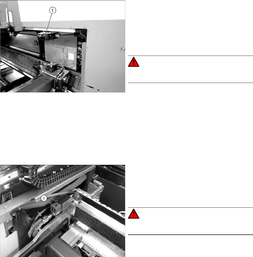
Cover switch
Safety Switch for the Component Trolley
► Open a protective cover. The other protective cover
must be closed.
► The control must switch off immediately. A message
should appear in the station software and you should
hear compressed air emerging.
If this is not the case, have the safety circuit checked
and any damaged components replaced by author-
ized personnel or the SIPLACE Service team.
DANGER!
Do not operate the machine while the safety circuit is de-
fective.
► Check the cover switch for damage. If there is any
damage, have the cover switch replaced by author-
ized personnel or the SIPLACE Service team.
► Check if the actuator moves cleanly and effortlessly
into the switching unit (1). If this is not the case, align
the actuator and cover switch with respect to one an-
other.
► Repeat these steps for all cover switches.
Check the safety switch (1) for the component trolley:
► Remove the component trolley. A message should
immediately appear on the control panel.
If this is not the case, have the safety circuit checked
and any damaged components replaced by author-
ized personnel or the SIPLACE Service team.
DANGER!
Do not operate the machine while the safety circuit is de-
fective.
► Repeat the procedure for all locations.