00196428-0102_AI_Reconfig_Kit_X-Serie_CPP_DE+EN.pdf - 第100页
2 Assembly Instructions Head Reconfiguration Kit CPP for the SIPLACE X Series Head Reconfiguration Kit 2.7 Installing the CPP Placement Head Issue 03/2010 100 X Connect all compressed air ho ses 2.7.5 Replacing the Servo…
Head Reconfiguration Kit 2 Assembly Instructions Head Reconfiguration Kit CPP for the SIPLACE X Series
Issue 03/2010 2.7 Installing the CPP Placement Head
99
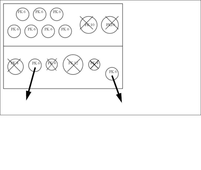
2.7.4.5 Connections at the Compressed Air Distributor
2
2
Designation Item no.
Plug QSC-6H 00337891-xx
Plug QSC-4H 00330249-xx
Plug QSC-8H 03010908-xx
Plug QSC-10H 00324874-xx
Plug QSC-12H 03015210-xx
Rear view of the pneumatic distribu
-
tor
Input:
7 fold flat tube (PK 6)
2 fo ld pn eumatic tu be ( vacuum
pump option PK10
not for CPP head and TwinHead)
Front view of the pneumatic distribu
-
tor
Output:
CPP head
Holding circuit 2
Pressure control valve / retract cylinder 2
2 Assembly Instructions Head Reconfiguration Kit CPP for the SIPLACE X Series Head Reconfiguration Kit
2.7 Installing the CPP Placement Head Issue 03/2010
100
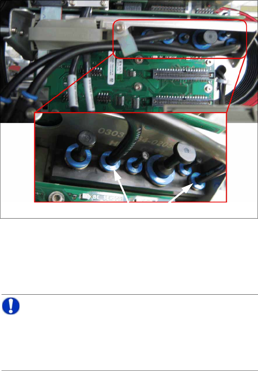
X Connect all compressed air hoses
2.7.5 Replacing the Servo Cards
X Open the door of the servo unit with the machine key.
X Insert the servo cards according to your machine configuration. (See Section 2.9.1 "Configu-
ration Axis Unit A364" on page 124.)
Connecting the compressed air hoses
NOTE:
When switching between C&P20, CPP and DLM C&P6/C&P12, the servo amplifier
SDS120/2,5S1 [00353445-xx] can be kept. 2
When switching between C&P20 and CPP, the DC/DC converter [03002397-xx] can be
kept. 2
When switching between C&P20 and CPP, only the Z axis servo card must be replaced.2
C&P20A: SDS60/2.5Z1 1 [03002143-xx] 2
CPP: SDS120/1.5Z2 1 [03070900-xx] 2
Head Reconfiguration Kit 2 Assembly Instructions Head Reconfiguration Kit CPP for the SIPLACE X Series
Issue 03/2010 2.7 Installing the CPP Placement Head
101
2.7.6 Installing and Setting the Height of the Nozzle Station
CAUTION:
Depending on the installation location (one-gantry placement area) the component trol-
ley docking unit must be released and pushed outwards. To do this, it is absolutely nec-
essary to read the relevant Service Manual. When the work is completed, the
component trolley docking unit must be refitted and all add-on parts (nozzle changer) re-
calibrated. 2
CAUTION:
Different nozzle stations are used for the X and the X4I series: 2
– Nozzle station CPx cplt. X Series [03073328-xx]
– Nozzle station CPP cplt. X4I [03074861-xx]
CAUTION:
The nozzle station only works with the new CAN node. From component trolley docking
unit [03015680-07] onwards, the CAN node is already included. Otherwise, it can be up-
graded by the Service. 2