00196428-0102_AI_Reconfig_Kit_X-Serie_CPP_DE+EN.pdf - 第98页
2 Assembly Instructions Head Reconfiguration Kit CPP for the SIPLACE X Series Head Reconfiguration Kit 2.7 Installing the CPP Placement Head Issue 03/2010 98 2.7.4.4 Settings of the Head Interface Board C500 X Check the …
Head Reconfiguration Kit 2 Assembly Instructions Head Reconfiguration Kit CPP for the SIPLACE X Series
Issue 03/2010 2.7 Installing the CPP Placement Head
97
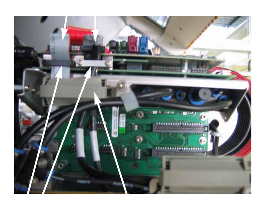
X Connect the two plugs of the component camera.
X Position the securing bracket in place and fix them with the screws.
X Close the cable clip.
2
Closing the cable clip
Connecting the plugs
Securing brackets
2 Assembly Instructions Head Reconfiguration Kit CPP for the SIPLACE X Series Head Reconfiguration Kit
2.7 Installing the CPP Placement Head Issue 03/2010
98
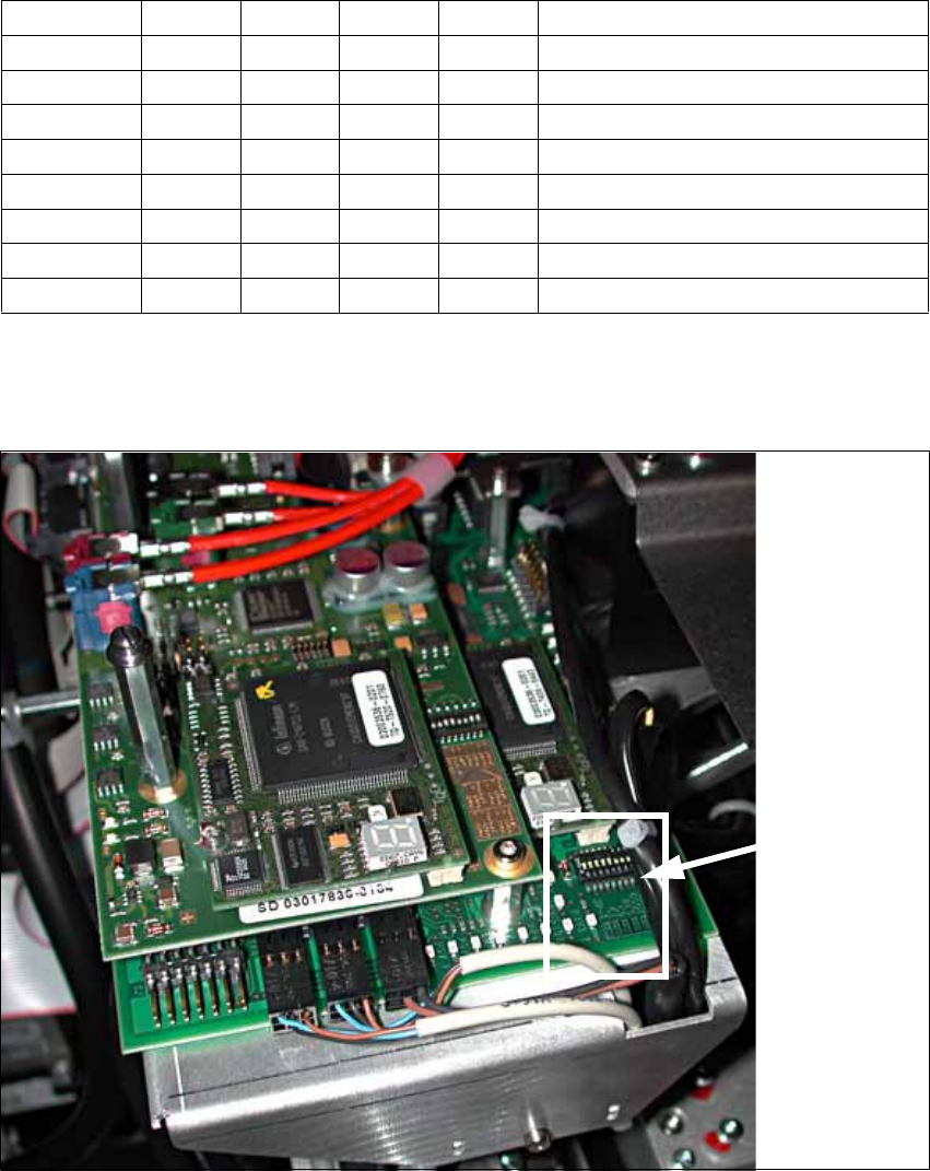
2.7.4.4 Settings of the Head Interface Board C500
X Check the jumper settings on the head interface board C500:
2
X In case of CAN bus problems, measure the resistance between pin 7 (CAN High) and pin 2
(CAN Low). It should be 60 Ohm.
2
Jumper Gantry 1 Gantry 2 Gantry 3 Gantry 4
1 0 1 0 1 Gantry ID0
2 0 0 1 1 Gantry ID1
3 1 1 1 1 120 Ohm CAN terminating resistor
4 0 0 0 0 Boot
5 0 0 0 0 Reset
6 0 0 0 0 CAN-ID0
7 0 0 0 0 CAN-ID1
8 0 0 0 0 Write protection released
Position of
the jumpers
Head Reconfiguration Kit 2 Assembly Instructions Head Reconfiguration Kit CPP for the SIPLACE X Series
Issue 03/2010 2.7 Installing the CPP Placement Head
99
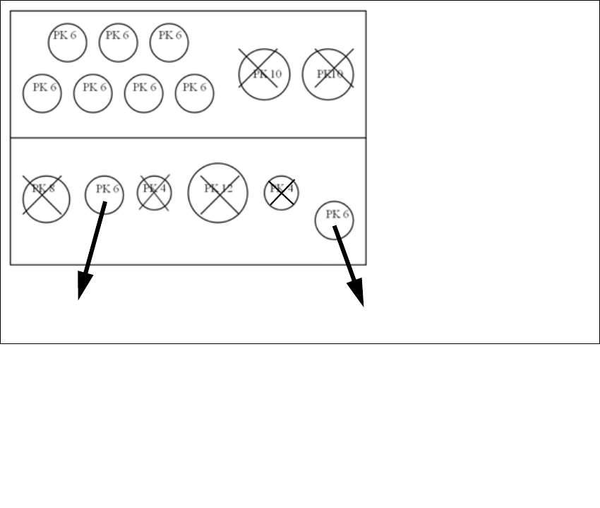
2.7.4.5 Connections at the Compressed Air Distributor
2
2
Designation Item no.
Plug QSC-6H 00337891-xx
Plug QSC-4H 00330249-xx
Plug QSC-8H 03010908-xx
Plug QSC-10H 00324874-xx
Plug QSC-12H 03015210-xx
Rear view of the pneumatic distribu
-
tor
Input:
7 fold flat tube (PK 6)
2 fo ld pn eumatic tu be ( vacuum
pump option PK10
not for CPP head and TwinHead)
Front view of the pneumatic distribu
-
tor
Output:
CPP head
Holding circuit 2
Pressure control valve / retract cylinder 2