00196428-0102_AI_Reconfig_Kit_X-Serie_CPP_DE+EN.pdf - 第81页
Head Reconfiguration Kit 2 Assembly Instructions Head Reconfiguration Kit CPP fo r the SIPLACE X Ser ies Issue 03/2010 2.7 Installing the CPP Placement H ead 81 2 – A docking frame of version -04 must not be reconfigured…
2 Assembly Instructions Head Reconfiguration Kit CPP for the SIPLACE X Series Head Reconfiguration Kit
2.7 Installing the CPP Placement Head Issue 03/2010
80
2
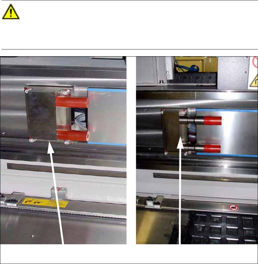
CAUTION: Danger of crashing
When using the CPP head together with an MTC the travel range must be restricted in
addition. To do this, install the 2 extensions for the Y axis stop
("Adaption Stop Y Axis MTC" [03075963-xx]) at the location with the MTC. These are
included in the Head Reconfiguration Kit. 2
Standard Y stop
Y stop for MTC with CPP
Head Reconfiguration Kit 2 Assembly Instructions Head Reconfiguration Kit CPP for the SIPLACE X Series
Issue 03/2010 2.7 Installing the CPP Placement Head
81
2
– A docking frame of version -04 must not be reconfigured.
2
– When using the CPP head together with the MTC, the crash light barriers on the feeding axis
of the MTC must be fitted at the low position. Please refer to the Assembly Instructions "MTC2
on Component Trolley Docking Unit X-S" [00194725-xx] for further details.
– For CPP heads in the high position that are used in conjunction with an MTC the lowest pickup
height with respect to the top edge of the board is -1.5 mm when the shortest nozzle is used.
Any edges protruding the tray must also be observed.
2
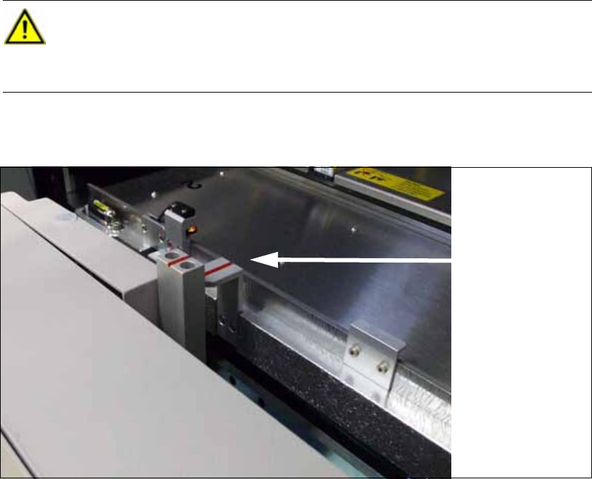
CAUTION: Danger of crashing
When using the CPP head together with the MTC, the "notch socket" positioning aid at
the docking frame of the MTC must be replaced. Install the 2 "notch sockets" [03010773-
02] (height: 103 mm). These are included in the Head Reconfiguration Kit. 2
Notch socket MTC
(standard)
2 Assembly Instructions Head Reconfiguration Kit CPP for the SIPLACE X Series Head Reconfiguration Kit
2.7 Installing the CPP Placement Head Issue 03/2010
82
2.7.2 Preparing the Head Plate
2.7.2.1 Checking the Pins on the Head and the Cooling Air Sealing
X Place the CPP template on the head fixture plate.
Remove excess screws and add the necessary ones:
Fixing screws: 4x DIN912 M4x18 - 8.8 [00095023-xx]]
Sealing screws: 9x DIN913 4x6 - ST [00309422-xx], secure with locking varnish, gray
[00318199-xx]!
If the head is not fixed correctly the cooling air flux might be disturbed.
X The other pins may protrude by max. 4.5 - 0.5 mm Please check these as well.
CAUTION:
Use standard tools only!
Make sure to use the correct screw lengths! The lengths for C&P heads differ from those
for TwinHeads. Torque of the fixing screws: 2.7 Nm.
If wrong screws are used, the threads in the head plate might be destroyed. 2
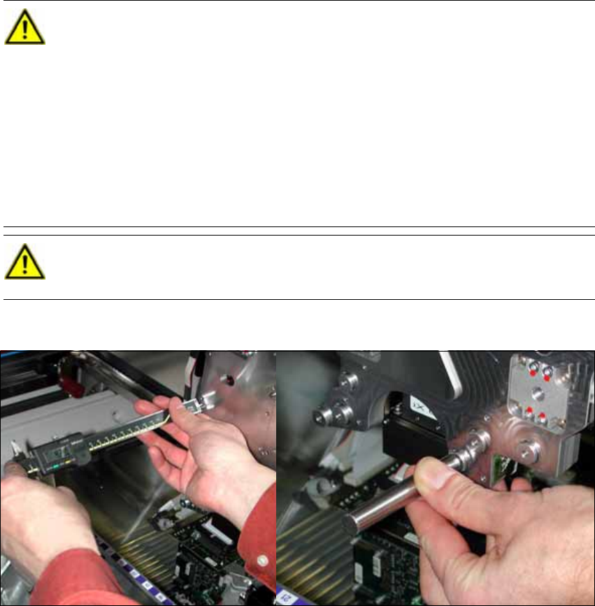
X Check the length of each pin of the head (2 items represented in dark green in the
figure) with a caliper or the testing tool for pin length 4 (-0.2) mm [03075779-xx].
These pins must not protrude more than 4 mm (-0,2 mm) from the head plate. If the
adjustment aid lays flush on the head plate without a gap the pin has been driven
deep enough into the head plate and can stay there.
CAUTION:
If pins with wrong lengths are used there is a danger of destroying the CPP head. 2