00196428-0102_AI_Reconfig_Kit_X-Serie_CPP_DE+EN.pdf - 第104页
2 Assembly Instructions Head Reconfiguration Kit CPP for the SIPLACE X Series Head Reconfiguration Kit 2.7 Installing the CPP Placement Head Issue 03/2010 104 X Install the valve for nozzle st at ion cplt. [03055785-xx] …
Head Reconfiguration Kit 2 Assembly Instructions Head Reconfiguration Kit CPP for the SIPLACE X Series
Issue 03/2010 2.7 Installing the CPP Placement Head
103
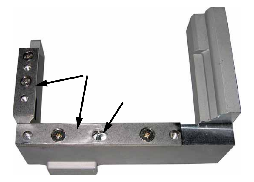
X If the distance is too large, insert shim plates:
Shim plate for nozzle reject device [03039514-xx and 03021079-xx],
screws DIN7991 M4x20 - 8.8 [00333782-xx].
2
X Remove the cover plate above the component reject bin.
Slot
Shim plates
2 Assembly Instructions Head Reconfiguration Kit CPP for the SIPLACE X Series Head Reconfiguration Kit
2.7 Installing the CPP Placement Head Issue 03/2010
104
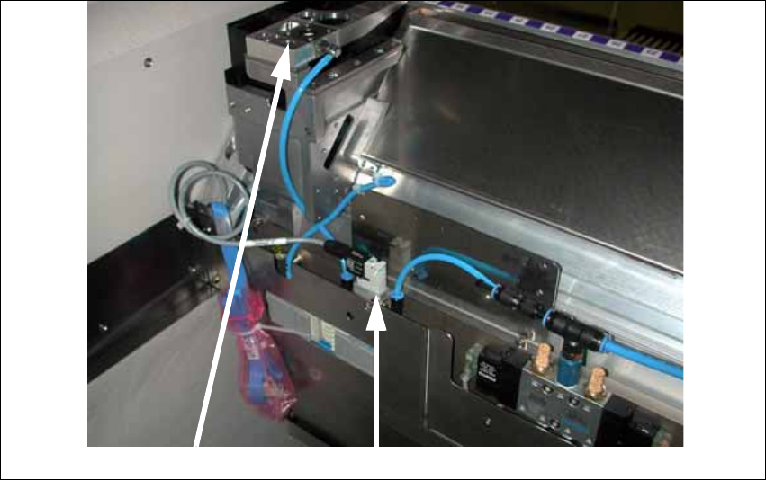
X Install the valve for nozzle station cplt. [03055785-xx] at the component trolley docking unit,
using the two DIN912-M3 x 16-A2-70 screws.
X Replace the plug QSC-H at the solenoid valve of the docking unit control by the "Y press-fit
connection with push-on socket QSY-6H-4" [03055792-xx].
X Connect the hose "PUN4 125 mm" with the Y press-fit connection with push-on socket and
the "valve for nozzle station cplt." [03055785-xx].
The second hole on the Y press-fit connection must be connected to the pneumatic hose of
the nozzle changer or closed with the plug QSC-4H.
X Connect the hose "PUN4 200 mm" to the "valve for nozzle station cplt." and the nozzle station.
X Connect the "Cable dock.unit X-series: nozzle station" [03053223-xx] that is already prewired
in the component trolley docking unit with the "valve for nozzle station cplt."
X Fix the "valve for nozzle station cplt." to the component trolley docking unit as shown in the
figure above, using two "DIN 7991-M4 x 20-8.8" [00333782-xx] / "DIN 912-M3 x 16-A2-70"
[00325349-xx] screws .
Insert the reject bin [03048638-xx] and the component reject bin up to 6x6 [03049954-xx]. On
older machines use version [03039042-xx ] instead of [03049954-xx]. The reject bin must not be
higher than the conveyor side in any case. 2
If the reject bin sensor is already installed, it must be repositioned for this reject bin. Use the sen-
sor mounting [03077835-xx] for this. See the Assembly Instructions Reject Bin Sensor SIPLACE
/ X-Series / D3 [00194716-xx] for more details. 2
Nozzle station Valve
Head Reconfiguration Kit 2 Assembly Instructions Head Reconfiguration Kit CPP for the SIPLACE X Series
Issue 03/2010 2.7 Installing the CPP Placement Head
105
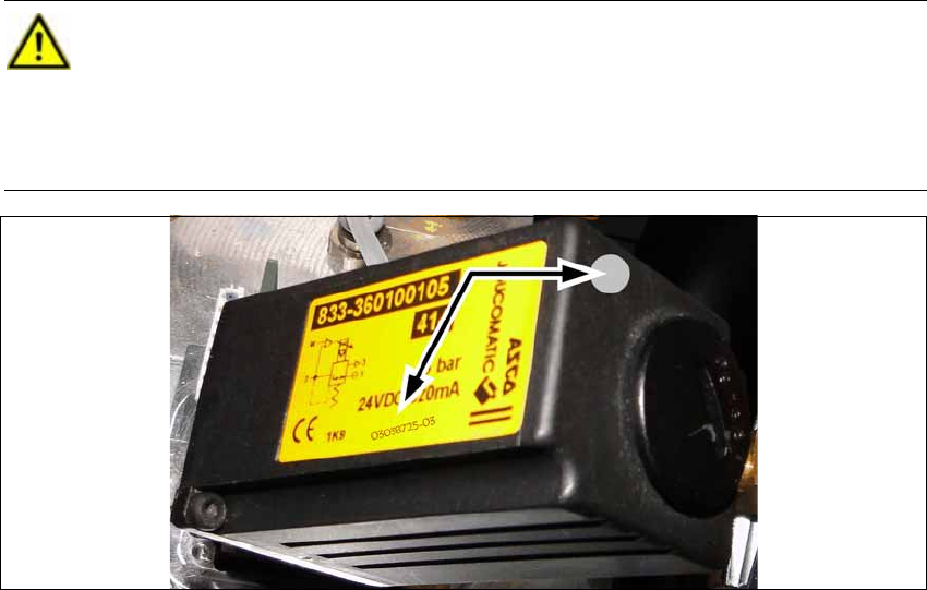
2.7.7 Pressure Regulator in the Pneumatic Supply
Correct the setting on the pressure regulator in the pneumatic supply. Read the technical informa-
tion TI2010-02C07. 2
2
CAUTION:
Not necessary for machines with pressure regulator 03038725 as of FS03 (see label). 2
Pressure regulators <FS03 that have already been set are indicated by gray lacquer or
are labeled with the item number. These must not be set again. If these are nevertheless
adjusted, the pressure regulator must be replaced. 2