00196428-0102_AI_Reconfig_Kit_X-Serie_CPP_DE+EN.pdf - 第120页
2 Assembly Instructions Head Reconfiguration Kit CPP for the SIPLACE X Series Head Reconfiguration Kit 2.8 Removing the Placement Head Issue 03/2010 120 2.8.5 Removing the Servo Cards X Remove the servo amplifier star , …
Head Reconfiguration Kit 2 Assembly Instructions Head Reconfiguration Kit CPP for the SIPLACE X Series
Issue 03/2010 2.8 Removing the Placement Head
119
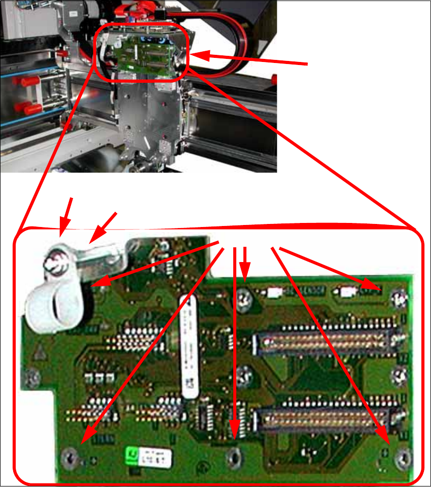
2.8.4 Removing the Head Adapter Board
X Remove the six screws and lift off the head adapter board (see photos below).
When switching to a C&P20 head this step can be omitted. In this case, however, the cable
holder must be reinstalled.
X Also remove the cable clip and the hexagonal bolt.
Head adapter board
6 screws
Cable clip
Hexagonal bolt
2 Assembly Instructions Head Reconfiguration Kit CPP for the SIPLACE X Series Head Reconfiguration Kit
2.8 Removing the Placement Head Issue 03/2010
120
2.8.5 Removing the Servo Cards
X Remove the servo amplifier star, Z axis and the DC/DC converter for the DP drives.
See also Section 2.7.5 "Replacing the Servo Cards" on page 100
When switching to a C&P20 head, the servo card star axis and the DC/DC converter can be
reused.
The servo amplifier of the Z axis must be removed in any case.
2
Head Reconfiguration Kit 2 Assembly Instructions Head Reconfiguration Kit CPP for the SIPLACE X Series
Issue 03/2010 2.8 Removing the Placement Head
121
2.8.6 Removing the Nozzle Station
When switching to a C&P 20 head the "nozzle station CPx cplt." X-Series" [03073328-xx] can be
reused. 2
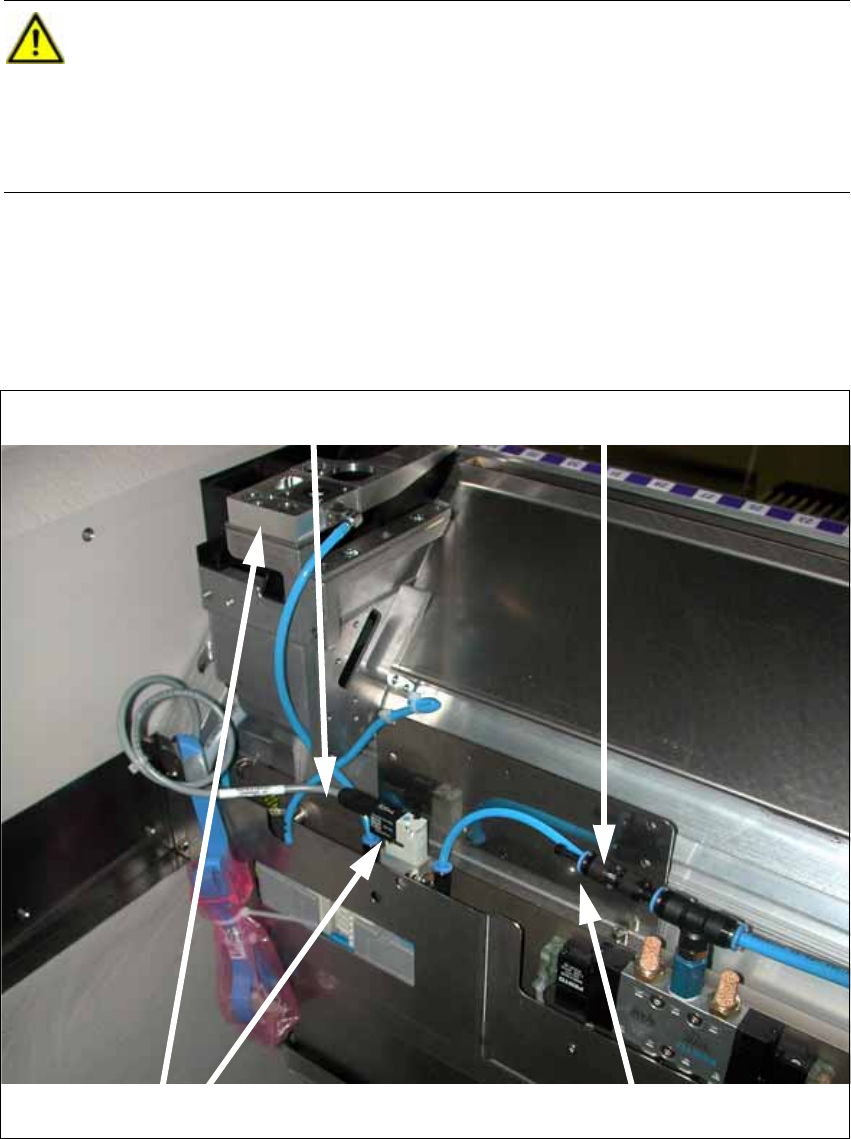
X Disconnect the cable from the solenoid valve (see photo below).
X Disconnect the Y distributor at the solenoid valve of the component trolley docking unit (see
photo below).
X Remove the nozzle station and the solenoid valve (see photo below).
X Close the T piece of the pneumatic supply with a plug QSC-4H [00330249-xx]
CAUTION:
Depending on the installation location (single gantry placement area) the component
trolley docking unit must be released and pushed outwards. To do this, it is absolutely
necessary to read the relevant Service Manual.
When the work is completed refit the component trolley docking unit and calibrate all
add-on parts (nozzle changer). 2
Cable at the solenoid valve
Disconnecting the Y distributor
Removing the nozzle station and the solenoid valve
Closing the T piece