[Superset] Chapter5_SPC Plus_ENG_20100827TW.pdf - 第24页
Programmer's Manual | 24 Saving Customer UCL/LCL and Customer USL/LSL set values This is the function of configuring the UCL/LCL va l u es . To use this func tion, proceed with the fo…
Programmer's Manual | 23
TosettheoptionsintheSPCConditiondialogbox,proceedwiththefollowing:
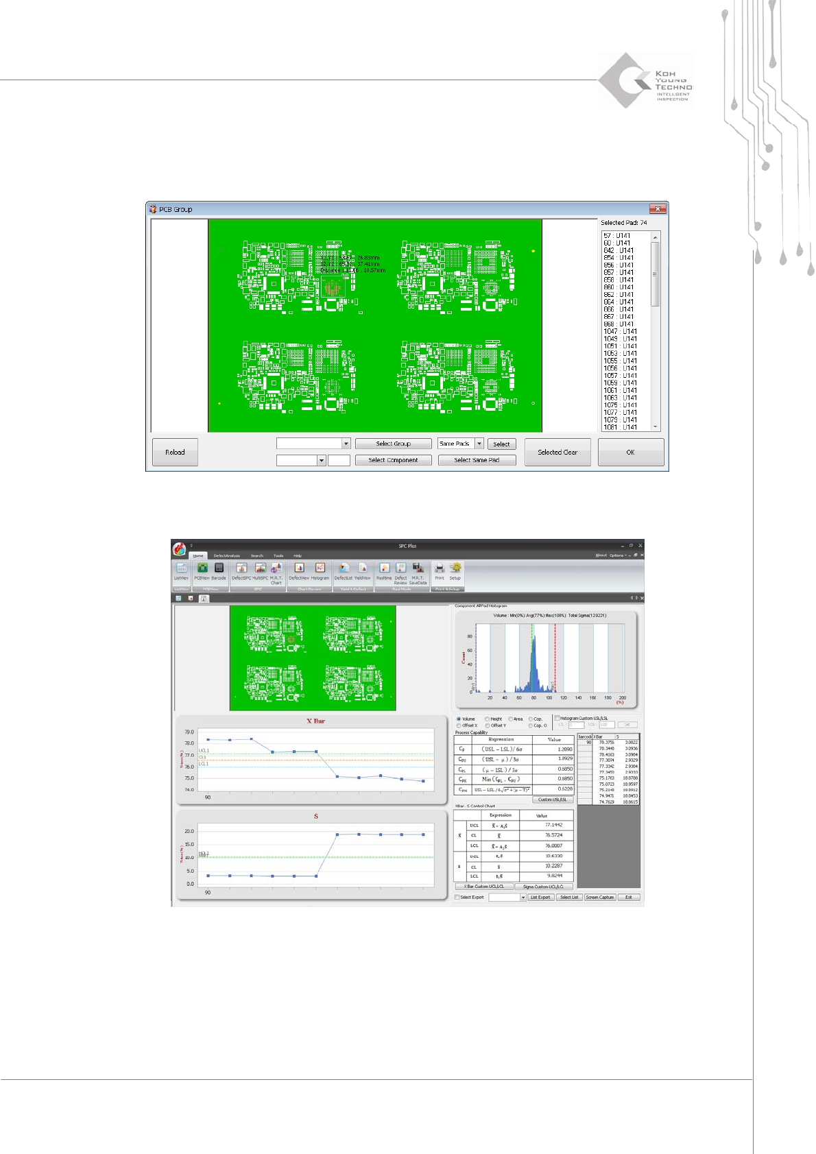
1. Select Group Pad from the SPC Condition dialog box and click the <Select Group> button. The PCB
Group dialog box will appear.
Figure 3-7. PCB Group
2. Select an area and click the <OK> button. Defect View for the corresponding area will appear.
Figure 3-8. DefectView
Programmer's Manual | 24
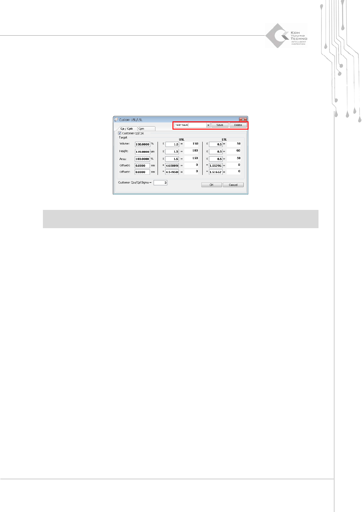
Saving Customer UCL/LCL and Customer USL/LSL set values
This is the function of configuring the UCL/LCL values. To use this function, proceed with the
following:
1. Click the <Custom USL/LSL> button in Process Capability on the lower right side of DefectSPC to
enable the Custom USL/LSL dialog box.
2. Select a Customer Cp/Cpk category as shown above to save the set values and click the <OK> button.
Note:UCL:UpperControlLimit:/LCL:Low erControlLimit:
USL:UpperSpecificationLimit:/LSL:LowerSpecificationLimit:
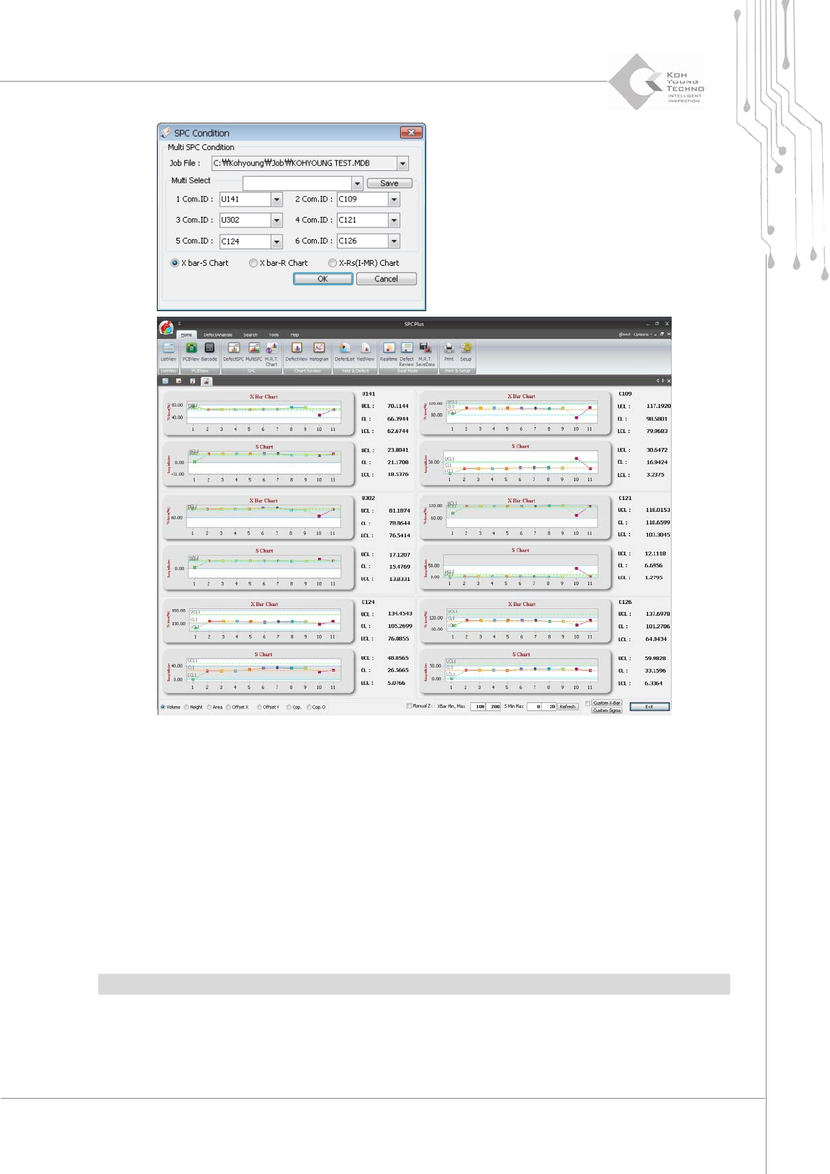
3.5. Multi-SPC
Multi‐SPC is the menu that simultaneously calculates the statistics of inspection results in the
various components. It is used for finding changes or problems per process period of pads with
specificComponentID.
Programmer's Manual | 25
Figure 3-9. Multi-SPC
Proceedwiththefollowingtousethismenu:
1. Select more than 2 PCBs from ListView and click the Multi-SPC icon.
2. The SPC Condition dialog box will appear.
3. Enter the desired ComponentID in the Multi-Select category and click the <OK> button. The Multi-SPC
screen will appear as shown above.
4. When a different component is selected from the selection window, the chart for the selected component
is updated accordingly.
Note:Upto6componentsareallow edforworkinMulti‐SPC.