192277 - Micron Technical Reference V9 Volume 1.pdf - 第236页
SQUEEGEE MODULE OVERVIEW 9.4 Technical Reference M anual Chapter Issue 8, May 19 Squeegee Drip Tr a y Figure 9-2 Squeegee Drip T ray Overview The squeegee drip tray mechanism secures to the underneath of t he print carri…
SQUEEGEE MODULE
OVERVIEW
Chapter Issue 8, May 19 Technical Reference Manual 9.3
Self Adjusting Paste
Deflectors (SAPD)
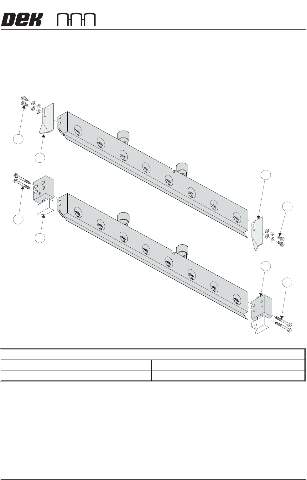
SAPD use a pair of deflectors which each have a piston that is spring loaded.
Once screwed in place, the deflectors self adjust with wear. These deflectors
are only available for 60 degree squeegees.
In the graphic below the differences between the standard paste deflectors (top
image) and the self adjusting type (bottom image) are evident.
Self Adjusting Paste Deflector - Exploded View
1 Paste Deflectors 3 Self Adjusting Paste Deflectors (SAPD)
2 Securing Screws and Washers 4 Securing Screws
1
2
4
3
3
4
2
1
1
2
4
3
3
4
2
1
SQUEEGEE MODULE
OVERVIEW
9.4 Technical Reference Manual Chapter Issue 8, May 19
Squeegee Drip
Tray
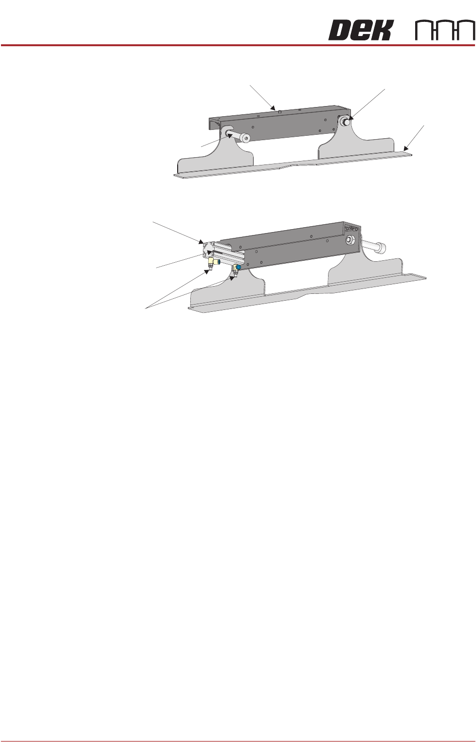
Figure 9-2 Squeegee Drip Tray Overview
The squeegee drip tray mechanism secures to the underneath of the print
carriage. The drip tray pneumatic actuator extends the drip tray below the
squeegees to prevent print medium from dripping onto the stencil during print
carriage initialisation or auto stencil loading.
The squeegee drip tray mechanism is also used to accommodate the auto
screen loader mechanism, refer to the Adjustable Screen Mount (ASM) or Cast
C Chase Module chapters for more information.
The drip tray retracted sensor is used by software to check that the pneumatic
actuator has retracted the drip tray before lowering the squeegees.
NOTE
With the squeegee drip tray and the screen depth adjuster fitted, the ASM must
be set to 29 inches and cannot accommodate smaller stencil sizes.
View on Rear of Squeegee Drip Tray
View on Front of Squeegee Drip Tray
Squeegee
Drip Tray
Squeegee Drip Tray
Securing Screw
Drip Tray Guide Shaft
Drip Tray Pneumatic
Actuator
Drip Tray
Retracted Sensor
Speed
Control Valves
Squeegee Drip Tray Mechanism
SQUEEGEE MODULE
ELECTRICAL SCHEMATIC
Chapter Issue 8, May 19 Technical Reference Manual 9.5
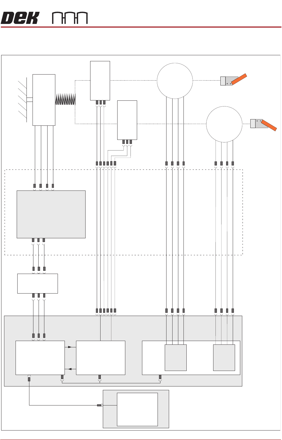
ELECTRICAL SCHEMATIC
Squeegee
Front
Home
(9SE04)
Squeegee
Rear
Home
(9SE05)
Rear
Squeegee
Stepper
Motor
(9M4)
Motor 1 B-
Motor 1 B+
Motor 1 A-
Motor 1 A+
Motor 2 B-
Motor 2 B+
Motor 2 A-
Motor 2 A+
Print Carriage
9PL16
9PL08
9PL17
0V
+V
-IN
+IN
Strain Gauge Bridge
(9SE6)
Spring Beam
9SK11
9SK12
Print Carriage I/O
Node 3
N3PL16
M36PL35
N3SK2
N6PL3
CAN BUS
PC
Mother
board
M36PL35
USB
M36Pl28
NextMove ES
(I/O Node 1)
NextMove
Interface
Dual Stepper
Card X2
M36 Machine Control
Step 3
Step 4
Front
Squeegee
Stepper
Motor
(9M3)
M36PL21
M36PL12
M36PL21
CAN
In
Rising
Table
Node 6
N6SK2