192277 - Micron Technical Reference V9 Volume 1.pdf - 第297页
PROFLOW MODULE CALIBRATIONS Chapter Issue 16, Nov 18 T echnical Reference Manual 11.15 NOTE Correct contact height is when the shim is just held between the transfer head wipers and stencil. At this position it is not po…
PROFLOW MODULE
CALIBRATIONS
11.14 Technical Reference Manual Chapter Issue 16, Nov 18
CALIBRATIONS
ProFlow Contact
Position Setup
To set up the ProFlow contact height position carry out the following procedure:
1. Select Open Cover Commands.
2. Select Carriage To Front.
3. Select Back.
4. Open the printhead cover.
5. Load the calibration stencil into the chase.
6. Fit an empty transfer head to the ProFlow pressure mechanism and remove
the ProFlow cover.
7. Position a 0.1mm shim on the stencil under the transfer head.
8. Close the printhead cover.
9. Press the System button.
10. Select Load Screen.
11. Select Maintenance.
12. Select Calibrations.
13. Select Classic Calibrations.
14. Select ProFlow.
15. Select ProFlow Heights.
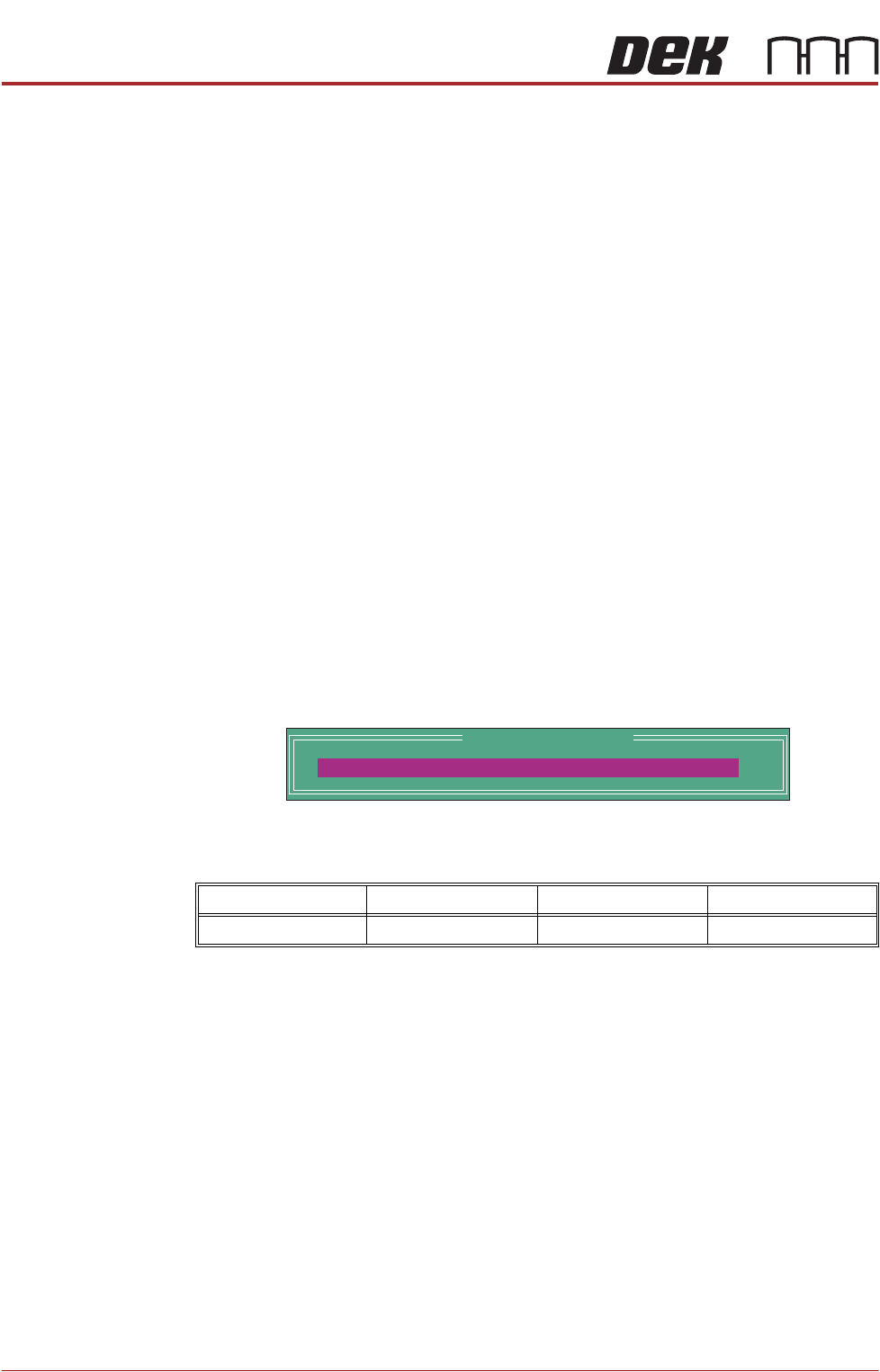
The following window and menu bar is displayed:
This parameter sets the height of the ProFlow printhead so that it just
touches the stencil surface.
16. Using the Incr. or Decr. keys, set the Contact Position to 5.5mm.
17. Select Move to Position, the ProFlow unit is driven to the position set.
18. Open the printhead cover.
Minimum Maximum Increment Default
- 10mm +10mm 0.1mm 0.0mm
ProFlow Calibrations
PFLOW CONTACT POS.
0.0
mm

PROFLOW MODULE
CALIBRATIONS
Chapter Issue 16, Nov 18 Technical Reference Manual 11.15
NOTE
Correct contact height is when the shim is just held between the transfer
head wipers and stencil. At this position it is not possible to slide the shim
sideways past the transfer head skis.
19. If correct contact height is achieved go to Step 25.
20. Close the printhead cover.
21. Press the System button.
22. Using the Incr. or Decr. buttons, increase or decrease the Contact Position
set height by 0.5mm (eg 5.0mm or 6.0mm).
NOTE
Normally the contact position is between 4mm and 8mm (nominally 6mm).
23. Select Move to Position, the ProFlow unit is driven to the position set.
24. Repeat Steps 17 to 22 to vary the set position until the correct contact height
is achieved.
25. Close the printhead cover.
26. Press the System button.
27. Select Exit.
28. Select Exit.
29. Select Exit.
30. Select Back.
31. Select Unload Screen.
32. Open the printhead cover.
33. Remove the shim
34. Remove empty transfer head.
35. Remove calibration stencil.
36. Close the printhead cover.
37. Press the System button.
ProFlow Transfer
Material
To set up the ProFlow sensor, carry out the following procedure:
1. Select Open Cover Commands.
2. Select Carriage To Front.
3. Select Back.
4. Open the printhead cover.
5. Ensure that the correct product stencil is fitted.
6. Fit an empty transfer head to the ProFlow pressure mechanism and remove
the ProFlow cover.
7. Close the printhead cover.
8. Press the System button.
9. Select Maintenance.
10. Select Calibrations.

PROFLOW MODULE
CALIBRATIONS
11.16 Technical Reference Manual Chapter Issue 16, Nov 18
11. Select Classic Calibrations.
12. Select ProFlow.
13. Select Transfer Material.
14. Select Set Empty.
15. The following message is displayed:
‘Confirm: Transfer head is fitted and empty?’
16. Select Confirm.
17. If prompted confirm that the correct stencil is fitted.
18. If prompted confirm that the correct ProFlow head size is fitted.
19. The following message is displayed:
‘The ProFlow unit will be placed at the rear of the image’
20. Select Confirm.
21. If prompted confirm that the ProFlow cover plate is removed.
22. The following messages are displayed:
‘Reading ProFlow Transfer Material Level...’
‘ProFlow Transfer Material Level set to Empty: 0%’
23. Select Change ProFlow.
24. ProFlow rises to the Home position.
25. If prompted confirm that the ProFlow base cover is fitted.
26. The print carriage moves to the front of the machine.
27. Open the printhead cover.
28. Remove the empty transfer head from the ProFlow pressure mechanism.
29. Fit a full transfer head to the ProFlow pressure mechanism.
30. Remove the cover.
31. Close the printhead cover.
32. Press the System button.
33. Select Continue.
34. If prompted confirm correct stencil is fitted.
35. If prompted confirm correct ProFlow head size is fitted.
36. The following message is displayed:
‘The ProFlow unit will be placed at the rear of the image’
37. Select Confirm.
38. Confirm ProFlow cover removed.
39. Select Set Full.
The message ‘Confirm: Transfer head is fitted and full?’ is displayed.
40. Select Confirm.
41. The following messages are displayed:
‘Reading ProFlow Transfer Material Level...’