192277 - Micron Technical Reference V9 Volume 1.pdf - 第267页
PROACTIV ADJUSTMENTS AND SETTINGS Chapter Issue 6, Nov 18 Techn ical Reference Manual 10.11 Squeegee Pressure Calibration A force meter calibration jig and a squeegee pressure plate are required to perform the squeegee p…

PROACTIV
ADJUSTMENTS AND SETTINGS
10.10 Technical Reference Manual Chapter Issue 6, Nov 18
ADJUSTMENTS AND SETTINGS
This section details the adjustments and settings required to set up the active
squeegee mechanism (it assumes that standard Squeegees have been fitted
to the printer).
Preparation 1. Power up and initialise the printer.
2. With the printer in the ready page; select Maintenance.
3. Select Machine Setup.
4. Select Options.
5. Select Pressure Hardware.
6. Select Fitted.
7. Select Accept.
8. Select Back.
9. Select Back.
10. Select Back.
11. Select Open Cover Commands.
12. If required, select Carriage To Front.
13. Open the printhead cover.
14. Remove the squeegees.
15. Clean and Stow the squeegees.
16. Close the printhead front cover.
17. Press the System Button.
18. Select Back.
PROACTIV
ADJUSTMENTS AND SETTINGS
Chapter Issue 6, Nov 18 Technical Reference Manual 10.11
Squeegee
Pressure
Calibration
A force meter calibration jig and a squeegee pressure plate are required to
perform the squeegee pressure calibration.
NOTE
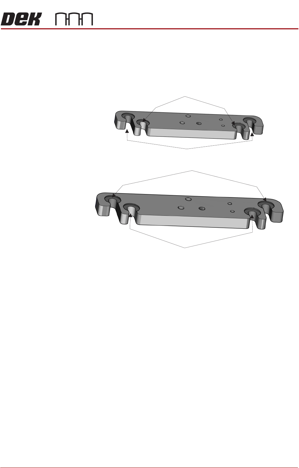
The front squeegee mount (foot) has two mounting locations, the inner locations
are for ProActiv, and the outer locations are for mounting the squeegee test jig.
Foot Assemblies
(showing the two squeegee mount locations)
Mount Locations for Pressure Test Jig or Standard Squeegee
Mount Locations for Standard Squeegee
Mount Locations for the Front ProActiv Squeegee Assembly
Mount Locations for the Rear ProActiv Squeegee Assembly

PROACTIV
ADJUSTMENTS AND SETTINGS
10.12 Technical Reference Manual Chapter Issue 6, Nov 18
NOTE
Ensure that the rising table print reference height is set correctly before com-
mencing, (the calibration relies upon accurate positioning of the table to make
a reference).
WARNING
BOARD CLAMPS. EXTREME CARE MUST BE EXERCISED WHEN WORKING IN
THE TOOLING AREA OF THE MACHINE TO AVOID INJURY. THE FOILS ON THE
FRONT AND REAR BOARD CLAMPS ARE VERY SHARP.
1. Select Open Cover Commands.
2. If required, select Carriage To Rear.
3. Select Unload Screen.
4. Open the printhead cover.
5. Remove the screen from the printer.
6. Remove the tooling from the tooling plate.
7. Close the printhead cover.
8. Press the System button.
9. Select Back.
10. Select Maintenance.
11. Select Calibrations.
12. Select Classic Calibrations.
13. Select Pressure.
14. Select Calibrat Readings. The rails are checked for the presence of a
board, the print carriage moves to the calibration position, the rear rail
moves to home position, the table homes and the board clamps are closed.
15. The machine cover is unlocked and the message ‘Calibrating Reading -
Fit pressure calibration rig.’ is displayed with the following window:
16. Open the printhead cover.
CALIBRATION DATA
Gain Factor
1.02